
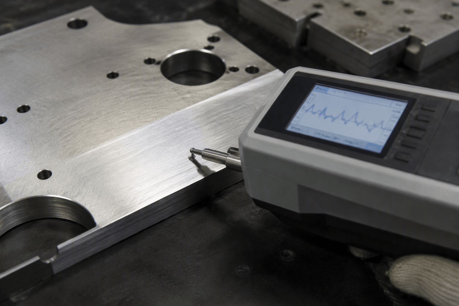
In the usual inch-based machining context, a 16 surface finish means 16 microinches Ra, which equals 0.4064 micrometers Ra and is commonly rounded to 0.4 micrometers Ra. It is not the same as 1.6 micrometers Ra, which is approximately 63 microinches Ra.
This interpretation is valid only when the drawing context establishes Ra as the roughness parameter and microinches as the units. A bare number 16 is not a complete surface specification.
How to Decode a 16 Surface Finish
Surface finish is a broad description of surface texture. Ra, one of the most commonly specified roughness parameters, expresses the arithmetic average of profile deviations over an evaluated length. Lower Ra values indicate smaller average deviations, but they do not automatically mean that a surface will perform better.
The conversion from microinches to micrometers uses the relationship 1 microinch = 0.0254 micrometers:
16 microinches Ra × 0.0254 = 0.4064 micrometers Ra
On a metric drawing, this may be written as Ra 0.4 µm after appropriate rounding. By contrast, Ra 1.6 µm converts to approximately 63 µin. Confusing these values would permit a surface with roughly four times the average profile deviation intended by a 16 µin Ra requirement.
Before production, confirm whether 16 refers to Ra, Rz, another parameter, a legacy grade designation, or something else defined by the drawing. The title block, general notes, local surface symbol, specified units, and governing drawing standard all provide context.
16 Surface Finish Conversion: Microinches Ra to Micrometers Ra
The following comparison places a 16 finish beside nearby Ra values. These are mathematical conversions, not statements that adjacent values are functionally interchangeable.
| Ra in microinches | Exact or approximate metric value | Practical interpretation |
|---|---|---|
| 8 µin | 0.2032 µm | Smaller average profile deviation than 16 µin Ra |
| 16 µin | 0.4064 µm, commonly 0.4 µm | The usual meaning of a 16 finish in an inch-based Ra context |
| 32 µin | 0.8128 µm, commonly 0.8 µm | Twice the numerical Ra value of 16 µin |
| 63 µin | 1.6002 µm, approximately 1.6 µm | The common inch equivalent of Ra 1.6 µm |
| 64 µin | 1.6256 µm | Sometimes confused with the rounded 63 µin conversion |
The conversion formula is straightforward, but selection is not. Changing a drawing from 16 µin Ra to 0.4 µm Ra preserves the intended roughness after rounding. Changing it to 1.6 µm Ra creates a materially different requirement.
Does the Part Function Justify 16 Ra?
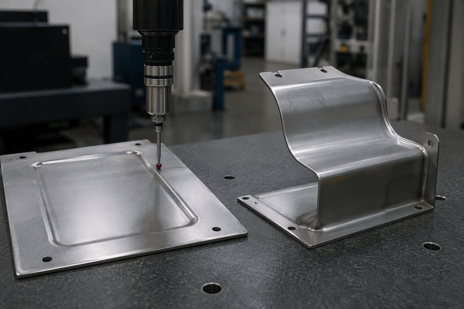
A 16 Ra requirement should follow the needs of the affected surface rather than a general preference for smooth parts. Mating geometry, material, hardness, coatings, lubrication, pressure, speed, contamination, and service life can all affect the appropriate texture.
| Surface function | Questions to resolve before specifying 16 Ra |
|---|---|
| Sealing contact | What seal type, pressure, fluid, mating material, and lay direction are involved? Ra alone does not control leak paths, scratches, waviness, flatness, or circular tool marks. |
| Sliding interface | What load, speed, lubricant, clearance, and wear mechanism apply? A smoother average profile may reduce some forms of friction, but the required texture depends on the complete tribological system. |
| Bearing or wear surface | Does the surface need lubricant retention, controlled running contact, or a specified break-in behavior? Other profile parameters may be relevant in addition to Ra. |
| Visible machined face | Are tool marks acceptable, and is appearance being judged visually or numerically? Two surfaces with similar Ra values can have different lay, reflectivity, scratches, and visible patterns. |
| Coating or bonding surface | Does the subsequent treatment require a particular texture or preparation method? A low Ra value is not automatically the best condition for coating adhesion. |
Specifying 16 µin Ra on every face can restrict tool paths, handling, inspection, and finishing without improving function. Conversely, omitting it from a critical interface can leave the supplier without a measurable acceptance criterion. Apply the callout only to the surfaces that need it and define separate cosmetic requirements when visible marks matter.
Ra also should not be used as a substitute for dimensional tolerances, flatness, waviness control, defect limits, or lay requirements. Those characteristics describe different aspects of the manufactured surface.
Production Factors Behind a 16 Ra Result
A specified roughness does not prescribe one universal manufacturing route. Material behavior, feature geometry, access, rigidity, tool condition, cutting parameters, and the direction of measurement relative to the lay can change the result.
| Operation or factor | Relevance to the finished surface |
|---|---|
| CNC turning | Tool nose geometry, feed, speed, workholding rigidity, runout, vibration, and material response influence the helical tool pattern on a rotational feature. |
| CNC milling | Cutter geometry, step-over, feed, tool condition, machine rigidity, entry and exit behavior, and toolpath direction affect both roughness and visible marks. |
| Grinding or honing | These operations may be considered when the required geometry and texture cannot be produced consistently by the preceding machining step. Their suitability remains feature- and material-dependent. |
| Polishing or lapping | Secondary finishing can modify texture, but it may also affect edges, dimensions, flatness, and the directionality of the surface. It must be planned with the dimensional requirements. |
| Inspection direction | A stylus trace taken across the dominant lay often produces a different result from a trace taken parallel to it. The agreed direction therefore matters. |
Put an Inspectable Requirement on the Drawing
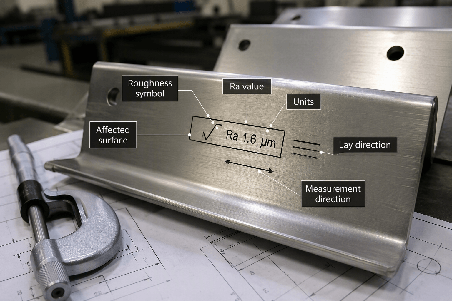
A useful callout identifies more than the number 16. A conceptual requirement might include Ra 0.4 µm, the affected surface, the applicable drawing standard, and lay direction where function makes it relevant. This is a checklist, not a universal symbol format; the notation must follow the standard and revision controlling the drawing.
Resolve these items during drawing review:
- Parameter and limit: State Ra, Rz, or the intended parameter and clarify whether the value is a maximum, range, or another defined limit.
- Units: Write µin or µm rather than relying on an undocumented shop convention.
- Affected area: Attach the symbol to the exact face or identify a bounded area. Do not leave critical and noncritical surfaces indistinguishable.
- Lay and trace direction: Define these when directional texture can affect sealing, sliding, appearance, or measurement repeatability.
- Standard: Identify the applicable drawing or surface-texture standard so symbol meaning and acceptance rules are understood consistently.
- Additional controls: Specify separate requirements for waviness, scratches, pits, coating preparation, or appearance when Ra cannot describe the acceptance condition.
Contact profilometry is a common way to verify Ra. The instrument traces a stylus across the surface and processes the profile according to selected measurement and filtering conditions. An agreed noncontact method may also be appropriate where a stylus could damage the surface, cannot access the feature, or does not suit the material.
A defensible inspection workflow is to clean the part without altering its texture, identify the specified measurement location, orient the trace as required, select the cutoff and evaluation length under the governing standard, apply the agreed filter, take the required number of traces, and report the result in the drawing units. Instrument condition, stylus geometry, surface access, vibration, and contamination can affect measurement quality.
Cutoff and evaluation length are not interchangeable. The cutoff helps separate roughness from longer-wavelength profile components, while the evaluation length defines the portion used for assessment. Inappropriate settings can produce different reported Ra values from the same physical surface.
If a local callout, general note, and title-block convention appear to conflict, do not infer acceptance from the lowest number. Resolve the conflict through the controlling drawing requirements before manufacturing or inspection.
For drawing clarification, provide Yishang with the drawing or marked-up callout, material, affected feature, roughness parameter and units, functional purpose, and expected inspection or reporting method. A review alongside the available custom CNC machining approach can determine whether the requirement is unambiguous and aligned with the intended production and verification route before production begins.
Frequently Asked Questions
What is the 16 rule for surface roughness, and is it the same as a 16 Ra callout?
The term may refer to a 16% acceptance rule used under certain surface-texture standards, under which a limited proportion of measured values may exceed an upper specified limit. It is not the same as a callout of 16 µin Ra. Acceptance rules depend on the governing standard, its revision, and how the limit is designated, so the drawing must establish which rule applies.
Is 16 microinches Ra equal to 0.4 micrometers Ra?
Yes, after normal rounding. The exact conversion is 16 µin Ra = 0.4064 µm Ra. Writing Ra 0.4 µm is the usual concise metric expression, provided the drawing’s rounding and acceptance conventions support it.
Is a 63 microinch finish equivalent to 1.6 micrometers Ra?
Approximately. Ra 63 µin converts to 1.6002 µm, while Ra 1.6 µm converts to about 62.99 µin. This is why 63 µin Ra, rather than 16 µin Ra, is commonly paired with 1.6 µm Ra in conversion charts.
Can a visual comparator confirm a 16 Ra requirement?
A comparator can support shop-floor assessment when its process pattern and lay resemble the part, but visual or tactile comparison is not a substitute for instrument measurement when numerical acceptance is required. Use contact profilometry or another agreed method with defined settings, locations, and trace direction. Visual requirements should be stated separately if scratches or tool-mark appearance also matter.