
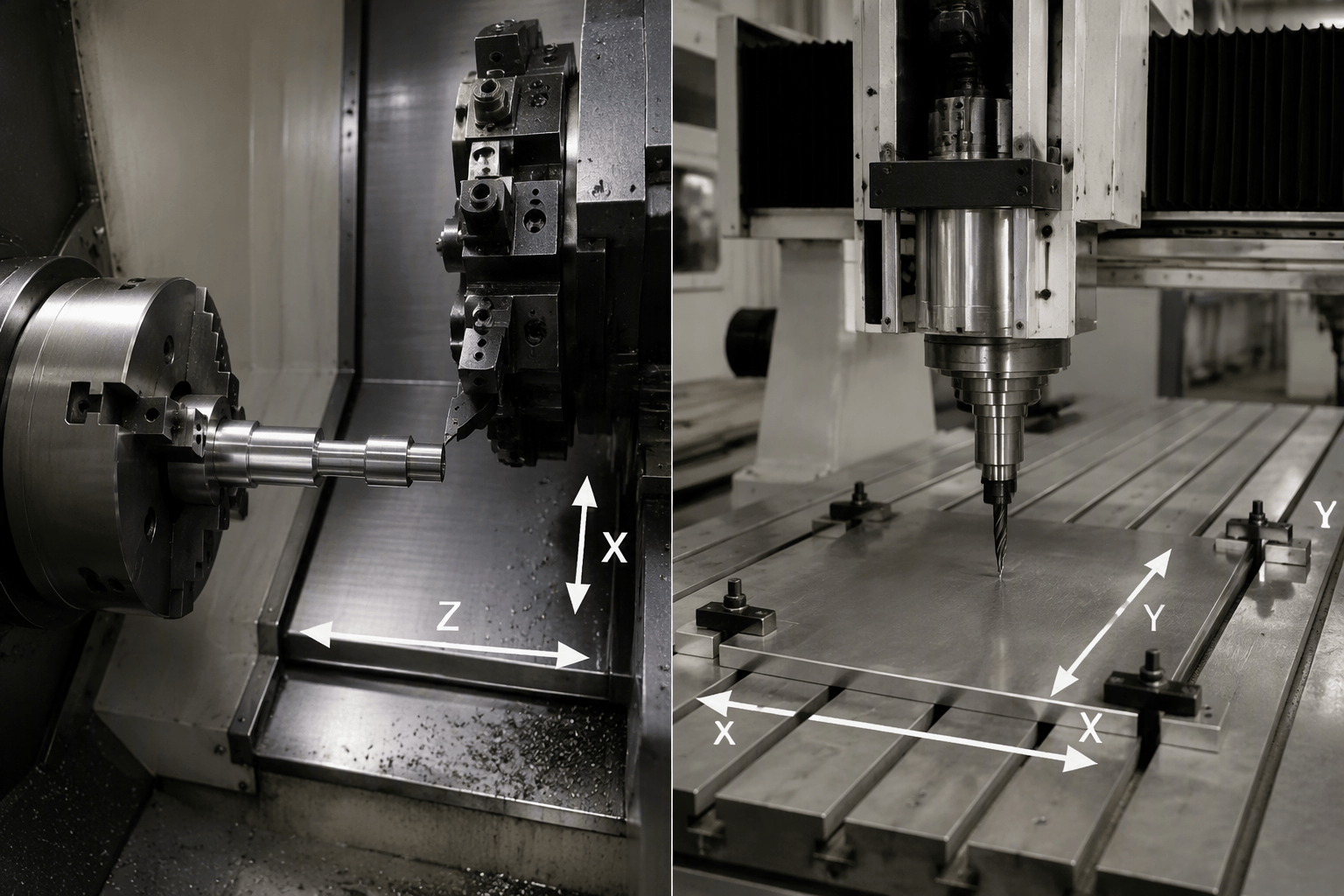
2 axis CNC describes a machine configuration with two CNC-controlled motion directions. It does not always mean X and Y. A basic CNC lathe commonly controls X and Z while the workpiece rotates. A planar milling or routing configuration may control X and Y while tool depth is fixed or set separately. The machine layout and the directions of the features on the drawing determine whether a part can be completed in one setup.
Axis count identifies controlled motion, not overall capability. It does not by itself establish accuracy, speed, material compatibility, part size, surface finish, or whether a particular feature is accessible. Those questions require the specifications of the actual machine, tooling, workholding, and process.
What Two Controlled Axes Mean on Different Machines
The linear axes X, Y, and Z describe straight-line movement. Rotary axes A, B, and C describe rotation about X, Y, and Z respectively. A machine called 2-axis therefore has two controlled directions relevant to its configuration, but the axis letters and the moving machine components can differ.
- X axis: linear motion along the machine’s defined X direction.
- Y axis: linear motion along the machine’s defined Y direction.
- Z axis: linear motion along the machine’s defined Z direction.
- A, B, and C axes: controlled rotation about X, Y, and Z.
An axis can be created by moving the tool, table, carriage, or workpiece. What matters is the relative motion between the cutting tool and the part. Machine documentation should identify both the axis direction and the component that moves.
Spindle rotation is not automatically a positioning axis. On a basic lathe, the spindle continuously rotates the workpiece to provide cutting speed while X and Z position the tool. The spindle becomes relevant as a controlled angular axis only when the machine can command its orientation or coordinate that orientation with another motion, as in an applicable C-axis configuration.
Lathe Motion Compared with Planar Milling or Routing
| Machine configuration | Typical controlled motion | What usually moves | Geometry created |
|---|---|---|---|
| Basic 2-axis CNC lathe | X and Z | The workpiece rotates in the spindle; the tool carriage moves radially and along the spindle centerline | Rotational profiles defined by diameter and axial position |
| 2-axis planar mill or router | Often X and Y, depending on the machine | The table, cutting head, or a combination of components moves in two linear directions | Profiles and features within the controlled plane |
How X-Z turning creates a profile
On a lathe, Z motion carries the tool along the length of the rotating workpiece. X motion changes the tool’s radial position and therefore the machined diameter. Coordinating X and Z can create stepped diameters, shoulders, tapers, faces, and curved profiles that remain rotationally symmetric about the spindle centerline.
This is why calling a basic lathe an X-Y machine is incorrect. Its primary lengthwise direction is conventionally Z, and X controls radial or diameter-related position. The rotating spindle supplies the cutting motion but does not, by that fact alone, add another positioning axis.
How two-axis milling or routing creates a planar path
In a planar configuration, two controlled linear motions position the cutter across a plane. Depending on the design, the table may move beneath a fixed spindle, the cutting head may move over a stationary workpiece, or motion may be divided between them. Coordinated movement can trace a contour, slot, pocket boundary, or hole pattern in that plane.
Depth still has to be established. On some machines it may be fixed, manually adjusted, or set in a separate operation rather than controlled as a third interpolating axis. A machine described as having a 2-axis controller may therefore differ mechanically from another machine carrying the same label. Its axis definitions and operating documentation must be checked before assigning a part.
Features That Fit Two-Axis Motion
Suitable geometry on a basic CNC lathe
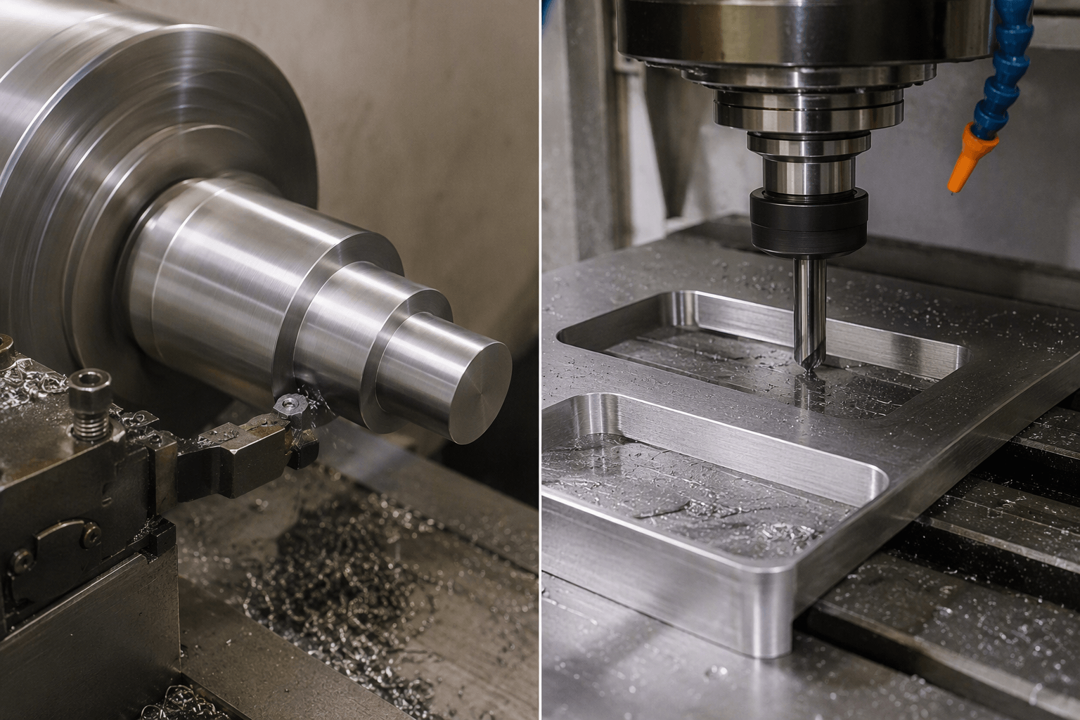
A two-axis lathe is a natural match when the required geometry is rotationally symmetric and accessible with X-Z tool motion. Depending on the setup and tooling, relevant features can include:
- Outside and inside diameters aligned with the spindle centerline
- Faces, shoulders, steps, grooves, and cutoffs
- Straight or profiled tapers generated through coordinated X-Z movement
- Axial bores or holes when the tool and setup support work on the centerline
- Threads or other rotational profiles when supported by the machine, control, and tooling
The important geometric test is not whether the drawing appears simple. It is whether each machined surface can be generated while the part rotates and the tool moves in X and Z. A cross-hole, an eccentric hole, a flat on the side, or a pocket away from the centerline does not follow that basic turning relationship.
Suitable geometry on a two-axis mill or router
Planar two-axis equipment suits features whose toolpaths remain in the controlled plane at an established depth. Examples can include:
- Two-dimensional outside profiles
- Slots and planar contours
- Pockets where the required depth can be set within the machine’s configuration and process
- Hole patterns whose centers lie in the controlled plane, provided drilling or cutting depth is handled by the available setup
- Engraved or trimmed paths on one accessible face
Features on another face, continuously changing three-dimensional surfaces, and cuts that require automatic tool inclination generally fall outside straightforward two-axis planar motion. Undercuts can also require different tooling, another setup, or another machine configuration because axis count alone does not guarantee tool access.
When Repositioning Extends the Process
A feature outside the initial motion plane does not always make the part impossible. The operator may flip, rotate, index, or refixture the workpiece so a different face becomes accessible. A lathe part may also move to another operation for side features that basic X-Z turning cannot create.
Multiple setups are not equivalent to simultaneous multi-axis machining. After repositioning, the machine still controls only its available axes; the new fixture orientation changes which part surfaces those motions can reach. Each setup also requires the part to be located from a usable datum. Relationships between features made in separate setups depend on how consistently that datum is transferred and how securely the part is held.
Consider three representative cases:
- Stepped round shaft: If all specified surfaces are concentric or axial and accessible from the chosen setup, X-Z turning may produce the main geometry directly.
- Flat plate with a profile and hole pattern: A planar two-axis path may suit the layout if depth is established appropriately and all features are accessible from one face.
- Round part with a side cross-hole: Basic X-Z turning creates the round profile but not the radial hole. The hole requires repositioning, a separate operation, or a machine configuration with the necessary spindle control and live-tool motion.
Repositioning may be practical for a limited number of accessible faces. If the drawing contains many related features on different orientations, angled holes, or surfaces that must be cut while orientation changes continuously, additional controlled axes may provide a more direct process.
Match the Feature Layout to the Required Axis Motion
| Feature layout | Likely motion requirement | Two-axis assessment |
|---|---|---|
| Concentric diameters, faces, grooves, and axial features | Radial and centerline-parallel tool motion with workpiece rotation | Commonly suited to an X-Z lathe when tooling and access support the features |
| Profiles, slots, or hole locations on one plane | Two controlled linear directions in that plane | Potentially suited to a planar mill or router if depth is handled by the configuration |
| Features on opposite or adjacent faces | New workpiece orientation or another controlled direction | May require flipping or refixturing; evaluate datum transfer and tool access |
| Off-axis or radial holes in a turned part | Angular positioning plus an appropriate cutting direction | Not produced by basic X-Z turning alone |
| Angled faces or holes | Angled setup, indexed orientation, or suitable additional axes | Possible only when the setup or machine supplies the required orientation and access |
| Three-dimensional surfaces changing in X, Y, and Z | Three coordinated linear directions, and sometimes rotary orientation | Generally requires more than planar two-axis control |
| Features around several sides with controlled orientation | Repeated indexing or rotary-axis motion | Compare multiple two-axis setups with an appropriate rotary-axis configuration |
A 3-axis machine adds another controlled linear direction, commonly allowing the tool to position in X, Y, and Z. Rotary axes add controlled orientation about one or more linear axes. They may index the part to a new angle between cuts or move simultaneously with linear axes, depending on the machine and program. Neither description should be inferred from a marketing label without checking the actual mechanical configuration.
Two-axis equipment is sufficient when every required feature can be reached and generated through the machine’s two controlled motions, spindle behavior, tooling, and planned setups. Consider three linear axes or suitable rotary motion when the drawing requires another feature direction, automatic access to multiple faces, off-axis work, or controlled orientation during cutting.
Evaluate the Drawing Before Selecting the Process
Start by marking the orientation of every machined feature. For a turned part, identify which features are concentric, axial, eccentric, or radial. For a milled or routed part, identify the working plane, required depths, accessible faces, undercuts, and angled details. Then compare those directions with the actual machine axes and determine whether any feature requires the part to be moved.
For a drawing-based process review, provide the part drawing or 3D model, material, required quantity, and the critical feature orientations or dimensions. This information supports an early decision about straightforward turning or milling, additional setups, or a different axis configuration. Once those requirements are established, review the available custom CNC machining service in the context of the actual geometry.
Where RFQ Assumptions Create Cost and Production Risk
Many sheet metal fabrication problems begin before production starts. If drawings, tolerances, finish expectations, material grades, or assembly requirements are unclear, suppliers may quote based on different assumptions. That can make prices difficult to compare and may lead to rework, cosmetic rejection, assembly misalignment, or production delays later.
For OEM buyers, the goal is not simply to request the lowest price. The goal is to make sure each supplier is quoting the same manufacturing reality. Before confirming an order, clarify which dimensions are fit-critical, which surfaces are cosmetic, whether prototypes must match batch-production conditions, and how finished parts will be inspected.
Frequently Asked Questions
What 2 axis cnc details should buyers define before requesting a quote?
Buyers should define the functional requirement, drawing notes, critical dimensions, material or process expectations, and any inspection points related to 2 axis cnc. This helps suppliers quote the same manufacturing scope instead of making different assumptions.
How can RFQ details affect cost, fit, or lead time?
RFQ details can change tooling, forming, welding, finishing, inspection, or rework requirements. If buyers do not clarify it early, two supplier quotes may look comparable while covering different production risks.
Why should drawing requirements be reviewed before prototype approval?
drawing requirements may look acceptable on a single sample but become harder to control during batch production. Buyers should confirm whether the prototype reflects the same process, finish, and inspection conditions expected for production.
What inspection points matter most for 2 axis cnc projects?
Important inspection points usually include fit-critical dimensions, holes or mating areas, cosmetic surfaces, finish build-up, welded or formed features, and any dimensions that affect downstream assembly. These points should appear in the RFQ or drawing notes.
How can buyers reduce prototype approval risk before batch production?
Buyers can reduce risk by clarifying drawings, locking key material and finish assumptions, defining inspection timing, approving a representative sample, and confirming which dimensions or surfaces require tighter process control.
How can Yishang help review 2 axis cnc requirements?
Yishang can review drawings, RFQ notes, material requirements, tolerance expectations, finish details, samples, and assembly needs to identify unclear assumptions before quoting or batch production.