
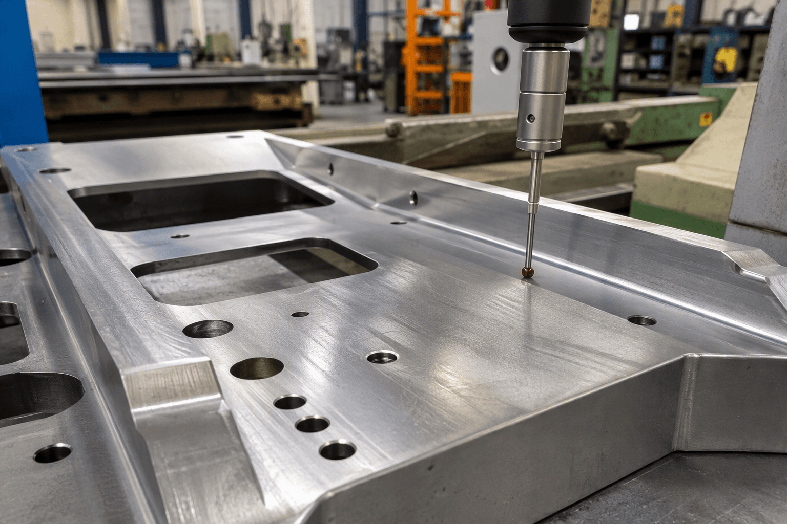
Ra 1.6 surface finish generally means an average surface roughness of 1.6 μm (micrometres), commonly expressed as approximately 63 μin (microinches). It is not a complete description of appearance, peak-to-valley defects, surface lay, coating, or the machining process used to produce the surface.
For OEM drawings, the most important question is not simply whether a part has a “smooth finish.” It is which roughness parameter applies, where it applies, how the surface will function, and how the supplier will verify it. A 1.6 surface finish may be appropriate for a sliding, sealing, bearing, or contact surface, but it can add process control and inspection effort when a less-refined finish would perform just as well.
What does a 1.6 surface finish callout actually measure?
Surface roughness describes the small-scale peaks and valleys left by a manufacturing process. Ra, or arithmetic average roughness, calculates the average absolute deviation of the measured profile from its mean line over a defined evaluation length. Therefore, Ra 1.6 means that the calculated average deviation is 1.6 μm under the specified measurement conditions.
The metric-to-imperial conversion is:
- Ra 1.6 μm ≈ 63 μin
- 63 μin ≈ Ra 1.6 μm
Rounding is normal in engineering documents, so a drawing may show 1.6 μm, 63 μin, or both. However, Ra is an average value. It does not set a maximum height for every individual peak or valley, and it does not automatically reject an isolated scratch, burr, dent, chatter mark, or other defect. If extreme profile height matters, the drawing may also need another parameter, such as Rz, together with a clear acceptance requirement.
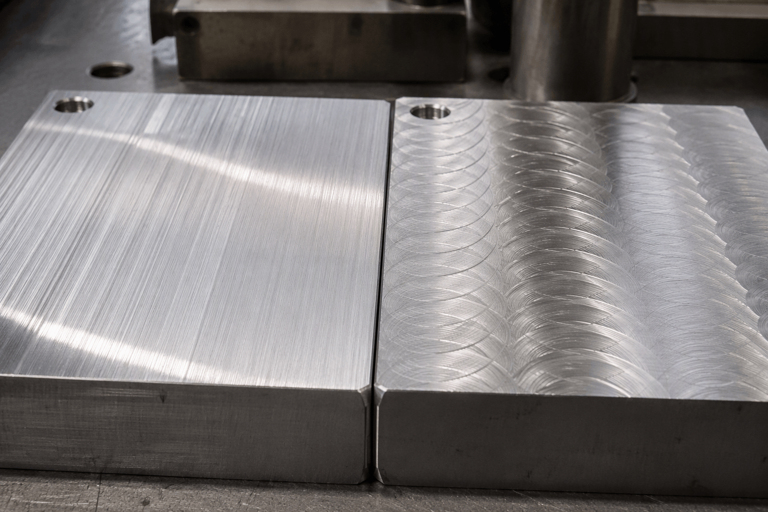
The broader phrase surface finish is often used informally to include roughness, waviness, visible marks, lay, and sometimes cosmetic appearance. These are not interchangeable. Surface lay is the predominant direction of the texture, such as the helical pattern from turning or the directional marks left by milling. Two surfaces can both measure Ra 1.6 and still look different because their lay, spacing, waviness, or visible tool marks differ.
Likewise, a roughness callout is not a coating specification. Paint, plating, anodizing, powder coating, gloss, color, and corrosion protection address different surface characteristics.
Surface-finish comparison: where does Ra 1.6 fit?
The table below uses commonly referenced roughness designations and rounded conversions. The process and application descriptions are practical examples, not guarantees. Actual results depend on alloy, hardness, thickness, geometry, tool condition, machine condition, and inspection method.
| Designation | Ra metric | Approx. imperial | Typical process routes | Possible application context |
|---|---|---|---|---|
| N5 | 0.4 μm | 16 μin | Fine grinding, honing, or controlled finishing | Specialized contact or sealing surfaces where the function justifies tighter control |
| N6 | 0.8 μm | 32 μin | Fine machining, grinding, or other controlled finishing | Selected bearing, sliding, or precision-interface surfaces |
| N7 | 1.6 μm | 63 μin | Controlled milling or turning; grinding may also be selected | Machined interfaces, sliding features, and general functional surfaces when justified |
| N8 | 3.2 μm | 125 μin | Common machining routes, depending on material and geometry | Many non-sealing, non-sliding machined surfaces where visible marks are acceptable |
| N9 | 6.3 μm | 250 μin | Rougher machining or less-refined process conditions | Non-critical surfaces where texture does not affect fit or function |
In this terminology, Ra 1.6 is normally associated with N7, not N6. N6 is commonly associated with Ra 0.8 μm. Because designation systems and drawing conventions can vary by region or company, it is safer to state the numerical Ra value and units rather than relying only on an N-grade.
A comparison chart should not be used as a universal process-capability table. A small, rigid component in a stable material may respond differently from a thin wall, deep pocket, interrupted cut, or long shaft. The same nominal Ra can also be produced by different routes, with different lay and visual results.
Why milling and turning can produce different texture
Milling: tool path and local geometry matter
In milling, cutter rotation and programmed feed leave a pattern that depends on feed per tooth, tool diameter, insert or end-mill geometry, step-over, axial engagement, and the direction of the tool path. A flat face may show regular marks, while a pocket floor, thin wall, or corner can show a different texture because the tool is deflecting or changing engagement.
Feed, speed, and tool geometry influence the theoretical and actual height of feed marks. A worn tool, unstable workholding, vibration, built-up edge, or a machine condition problem can increase roughness or create visible chatter even when the programmed parameters appear suitable. Material behavior is also important: ductile alloys, abrasive materials, gummy materials, and harder steels may produce different cutting responses.
Turning: feed marks and circumferential lay
Turning commonly produces a texture that follows the tool’s movement around the workpiece. Feed rate, insert nose radius, cutting speed, depth of cut, workpiece support, and tool condition all affect the resulting profile. A turned diameter may have a generally circumferential or helical lay, which can be important for lubrication retention, sliding direction, or sealing behavior.
Turning direction and the way a mating component moves over the surface should be reviewed together. A measured Ra value alone does not explain whether the lay is favorable for the application. Workholding can also influence results on long, slender, or thin-walled parts because deflection and vibration may vary along the feature.
Secondary operations such as grinding, honing, polishing, or controlled abrasive finishing may be considered when the required roughness, lay, or appearance cannot be reliably obtained from the primary cut alone. That decision should be based on the actual material, geometry, production quantity, and inspection evidence rather than on the Ra number in isolation.
Visible tool marks deserve a separate note. Marks can be visually noticeable while the measured Ra remains within the specified value, and a visually uniform surface can still contain a peak or defect that an average value does not describe. If appearance matters, add a cosmetic requirement or reference sample instead of assuming Ra 1.6 defines visual quality.
How to specify and verify Ra 1.6 on an OEM drawing
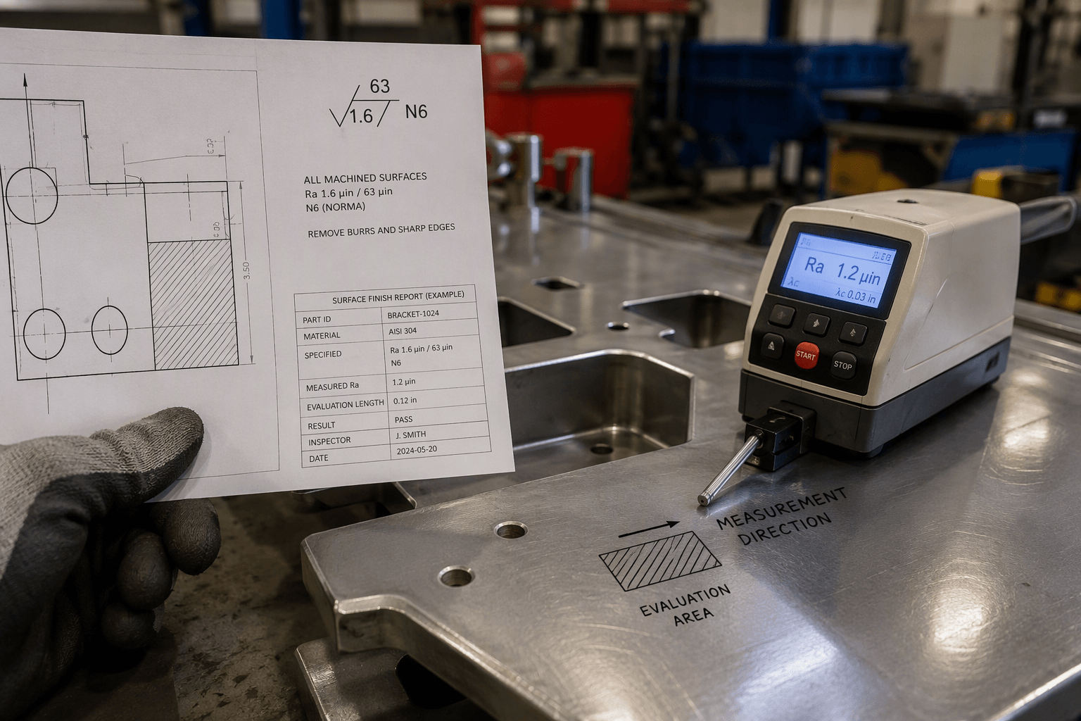
A production-ready callout should identify the parameter, target, units, and surface location. For example, a drawing might identify Ra 1.6 μm on a particular bore, face, seal land, or sliding diameter. The relevant surface should be unmistakable, especially when only one face of a machined component has the requirement.
Where function depends on texture direction, include the required lay or state that the supplier must review it. Where visible marks are unacceptable, describe that expectation separately. If a coating or plating follows machining, clarify whether the roughness applies before coating, after coating, or at both stages. Coating thickness and process buildup can change the final measured profile.
Buyer and supplier should also agree how verification will be performed. Important questions include:
- Which parameter is reported: Ra only, or Ra together with Rz or another value?
- In which direction will the instrument traverse relative to the lay?
- What evaluation or sampling conditions apply?
- Where on the feature will measurements be taken, and how many locations represent the surface?
- Will the result be reported as an individual reading, an average, or a range?
- How will scratches, burrs, waviness, chatter, and other isolated defects be handled?
Measurement direction matters because a probe crossing the lay can record a different profile from one moving along it. Instrument method, cutoff and evaluation settings, surface cleanliness, operator technique, and measurement location can all affect the reported result. A supplier should not be expected to infer these details from the words “smooth finish.”
If the surface is part of a bearing, seal, fatigue-critical interface, or precision sliding feature, the drawing should connect the numerical requirement to the engineering function. Ra 1.6 may be useful, but it may not be sufficient to control waviness, isolated defects, form, roundness, coating condition, or surface integrity.
When is Ra 1.6 worth specifying?
Use the functional requirement as the starting point, then select the roughness target. Ra 1.6 may be justified in the following situations:
- Wear and friction: A controlled texture can support predictable contact between moving surfaces, but the correct value depends on materials, load, speed, lubrication, and motion.
- Lubrication: Lay and profile shape can influence how lubricant is retained or displaced. The numerical Ra alone does not determine lubrication performance.
- Sealing: A seal land may need controlled roughness and lay, but seal type, pressure, material, hardness, and defects also matter.
- Fatigue: Lower roughness can reduce some surface notch effects, yet fatigue performance also depends on geometry, material condition, residual stress, loading, and manufacturing history.
- Bearing or precision interfaces: A specified roughness may help control contact behavior, but form, runout, roundness, alignment, and cleanliness may be equally important.
Ra 1.6 may be unnecessary on a concealed bracket face, a non-contact enclosure surface, or a feature where visible machining marks and a higher roughness do not affect assembly. Requiring it everywhere can increase tool-control requirements, secondary finishing, inspection time, handling risk, and the chance of rework or scrap. The cost impact is not a universal percentage: it changes with material, feature accessibility, geometry, volume, process route, and documentation requirements.
Ra 1.6 surface-finish decision table for production planning
| Decision item | What to record before release |
|---|---|
| Functional surface | Identify the exact face, bore, diameter, seal land, or contact feature. |
| Roughness parameter | State Ra 1.6 μm or the required parameter and value; do not rely on “fine finish” alone. |
| Units and grade | Use metric, imperial, or both. If an N-grade is included, confirm that it matches the numerical value. |
| Lay and appearance | Define lay direction, visible-mark expectations, or cosmetic references when relevant. |
| Material and geometry | List alloy, hardness if controlled, wall thickness, pocket depth, diameter, interruptions, and access limits. |
| Process route | Identify the proposed milling, turning, grinding, honing, or other finishing route without assuming capability. |
| Measurement method | Agree instrument direction, evaluation conditions, locations, readings, and reporting format. |
| Acceptance language | Define whether Ra is the only criterion and how isolated defects, waviness, or Rz will be treated. |
For a technical feasibility review, share the part drawing or relevant surface callout, material, production quantity, preferred machining route if already defined, functional reason for the finish requirement, and inspection or reporting expectations. The review should assess whether the specified roughness, process route, measurement method, and acceptance language match the part’s actual function before production planning. For machining context, see custom CNC machining from first sample to repeat production.
Frequently Asked Questions
Is a surface finish of 63 μin equivalent to Ra 1.6 μm?
Yes, approximately. Ra 1.6 μm converts to about 63 μin, and 63 μin converts back to roughly 1.6 μm. Because both values are commonly rounded, drawings should state the intended parameter and units clearly.
What does Ra 1.6 mean, and how is it different from Rz?
Ra 1.6 is an arithmetic average of profile deviations from a mean line over a defined evaluation length. Rz is a height-based roughness parameter that is more sensitive to peak and valley amplitude. Ra does not by itself define the maximum isolated defect or every feature of the profile.
What does the N6 designation mean compared with Ra 1.6?
N6 is commonly associated with Ra 0.8 μm, or approximately 32 μin. Ra 1.6 μm is commonly associated with N7, approximately 63 μin. Since designation conventions can vary, include the numerical Ra value rather than using only an N-grade.
Can a standard CNC milling or turning process consistently produce Ra 1.6 on every surface?
Not automatically. Achieved roughness depends on material, tool geometry, feed, speed, tool wear, machine condition, workholding, feature geometry, and measurement conditions. A supplier should review the actual part and confirm the process and inspection plan rather than treating Ra 1.6 as a universal guarantee.
When a 1.6 surface finish appears on a drawing, treat it as a measurable functional requirement—not a complete visual description. Define the surface, parameter, lay, process assumptions, and verification method before production planning.