
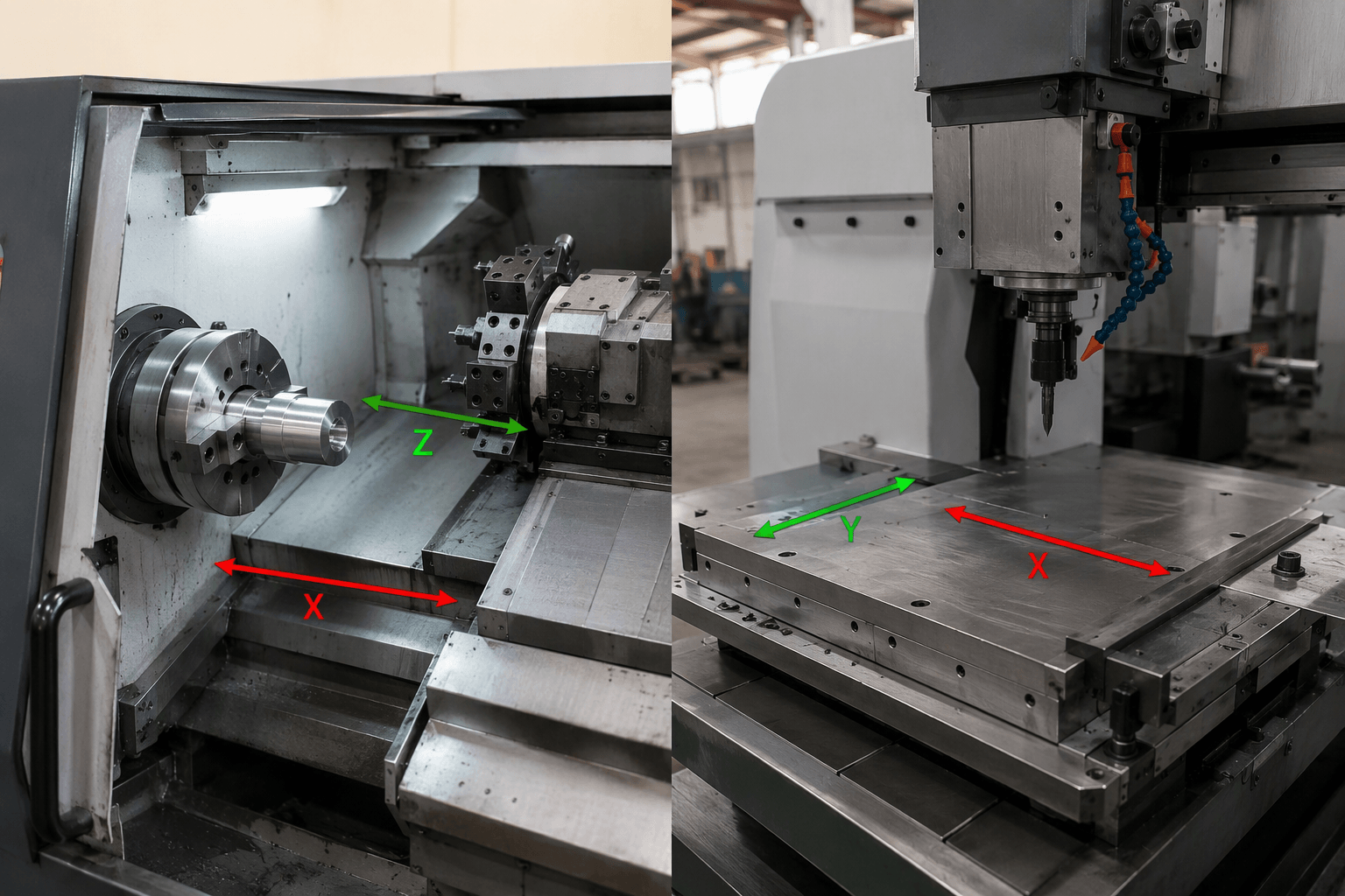
2-axis CNC means that a CNC system controls motion along two machine axes during an operation. Those axes are commonly X and Z on a CNC lathe, while a planar mill, router, cutting machine, or engraver may use X and Y.
The useful question is therefore not only how many axes a machine has, but also which components move, how the workpiece is oriented, and whether the required features can be reached in one setup.
What Counts as an Axis in CNC Machining?
An axis is a controlled linear or rotary motion defined by the machine architecture and CNC controller. Multiple axes can move separately or in coordination to place a cutting tool relative to a workpiece.
The three conventional linear axes are X, Y, and Z. Their physical directions depend on the machine coordinate system, but Z is generally associated with the principal spindle direction. Rotary axes are designated A, B, and C, corresponding to rotation around X, Y, and Z respectively.
| Axis | Motion type | General meaning |
|---|---|---|
| X | Linear | Controlled movement along the machine’s X direction |
| Y | Linear | Controlled movement along the machine’s Y direction |
| Z | Linear | Controlled movement along the machine’s Z direction, commonly aligned with the spindle axis |
| A | Rotary | Rotation around X |
| B | Rotary | Rotation around Y |
| C | Rotary | Rotation around Z |
The term “2-axis CNC machine” does not identify a universal pair of directions. A basic CNC lathe normally controls X and Z tool motion while the workpiece rotates in the spindle. A planar engraving or profile-cutting system may control X and Y while maintaining a fixed working height. The machine type must be identified before an axis count becomes meaningful.
How Two-Axis Machine Architectures Differ
The main architectures place motion in different components. Depending on the design, the tool carriage, spindle, workpiece, or machine table may move. The following comparison separates turning from planar machining rather than grouping every two-axis machine under the same description.
Two-axis CNC lathe: X and Z tool movement
On a conventional two-axis CNC lathe, a chuck or collet holds and rotates the workpiece. The cutting tool is mounted on a carriage or turret that commonly moves along X and Z. Z travel follows the workpiece’s rotational axis, while X travel moves the tool toward or away from the centerline and controls diameter.
Rotating workpiece: spindle rotation
Z: tool moves along the workpiece length →
X: tool moves toward or away from the centerline ↑
This arrangement supports turning operations on rotational parts. It should not be described as X-Y machining, because the coordinate convention and relationship between tool and workpiece are different.
Two-axis mills, routers, cutters, and engravers
A planar 2-axis CNC configuration controls movement in two linear directions, often X and Y. The tool may travel over a stationary workpiece, the table may carry the workpiece under a stationary spindle, or each direction may be split between the table and tool assembly. What matters is the resulting relative motion.
Workpiece: fixed to a table or moved by the table
X: tool or table moves left and right ↔
Y: tool, gantry, or table moves forward and back ↕
Operations may include profile cutting, slotting, hole patterns, marking, or engraving, but only when the spindle, tooling, workholding, material, and machine construction support that operation. Axis count by itself does not establish whether a system can machine metal, plastic, wood, or another material effectively.
Geometry a 2-Axis CNC Can Produce in One Setup
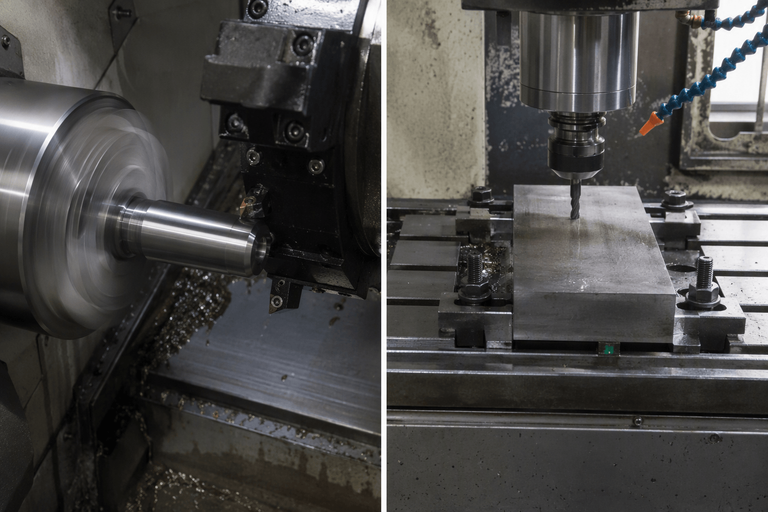
A two-axis toolpath can contain many lines, arcs, and coordinated movements. That does not give the machine access to every feature orientation. The practical limit is the geometry reachable through the available motions without unclamping, rotating, or reorienting the workpiece.
Rotational features on a two-axis lathe
A basic X-Z lathe is suited to features arranged around the spindle centerline. Representative operations include facing an end, turning external diameters, producing shoulders, cutting circumferential grooves, and generating straight or tapered profiles. Depending on the machine and tooling configuration, it may also drill, bore, or thread features aligned with the spindle axis.
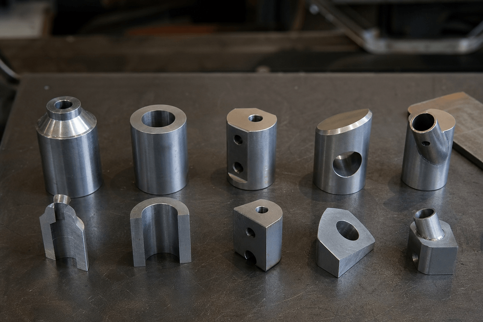
For example, a stepped shaft with concentric diameters and a centered axial hole may fit the architecture. A cross-hole through the side of that shaft does not. The cross-hole has a radial orientation and normally requires a secondary drilling setup or equipment capable of positioning the part and driving an appropriate tool.
Planar features on a two-linear-axis machine
An X-Y system can trace a two-dimensional outline, open slot, engraving path, or hole pattern from one accessible orientation. It may also produce nested cut profiles in sheet or plate when the cutting process and material are compatible.
However, the tool cannot follow a programmed depth contour without a controlled depth axis. A second machined face, angled hole, side feature, or true three-dimensional surface also falls outside a single X-Y setup. A fixed cutting depth can support a 2D path, but it should not be confused with coordinated X-Y-Z machining.
Undercuts require separate consideration. Even a machine with more axes cannot make an undercut unless the feature is physically accessible and a suitable tool can enter and clear it. Tool shape, spindle access, fixtures, and collision limits remain relevant regardless of the nominal axis count.
Repositioning, Indexing, and Additional Axes
When the available axes cannot present a feature to the tool, production may require another setup or a different machine architecture. These options affect process planning in distinct ways.
- Manual repositioning
- The operator unclamps the part, turns or flips it, establishes the next orientation, and clamps it again. This can expose a second face or radial feature, but the new setup introduces another datum relationship. Workholding, locating surfaces, and setup method influence how consistently features from separate operations relate to one another.
- Indexed positioning
- A rotary device positions the workpiece at a specified angle and holds it while machining occurs. Indexing can reduce manual handling, but indexed motion is different from continuously coordinated rotary machining. The exact capability depends on how the rotary device and controller are integrated.
- Three-axis linear machining
- A standard 3-axis mill controls X, Y, and Z. It can vary depth while following a planar path, machine pockets and contoured surfaces within tool-access limits, and combine features at different depths. It does not independently rotate the part simply because it has three axes.
- Machining with rotary axes
- An added A, B, or C axis can orient or rotate a tool or workpiece. Some processes index the rotary axis between cuts; others coordinate rotary and linear motion simultaneously. These are different capabilities and should be confirmed from the proposed machine and process, not inferred from a broad axis label.
A C-axis is not part of a basic two-axis lathe. On an appropriately configured turn-mill machine, spindle positioning or controlled rotation can work with driven tooling to produce features such as flats or off-center holes.
Can This Geometry Be Made With Two Controlled Axes?
Start with the drawing rather than the machine label. Identify the primary part form, mark every machined feature by direction, and count the orientations from which a tool must approach. Then consider whether the workpiece can remain on one reliable datum throughout the process.
| Drawing characteristic | Likely architecture | One two-axis setup? | Planning note |
|---|---|---|---|
| Concentric diameters, shoulders, grooves, or a taper | X-Z CNC lathe | Often possible | Features must be accessible as the workpiece rotates around one centerline. |
| Centered hole along a turned part’s spindle axis | X-Z CNC lathe | Potentially possible | Depends on the machine, workholding, tooling, hole geometry, and access. |
| Flat 2D profile, slot pattern, or engraving from one direction | X-Y planar machine | Often possible | The selected machine and cutting process must support the material and required depth. |
| Features at several controlled depths | Three-axis mill | Generally not on fixed-depth X-Y equipment | Controlled Z motion is needed when depth changes are part of the programmed toolpath. |
| Machining on opposite or adjacent faces | Repositioned setup, indexed fixture, or additional-axis machine | Not in one fixed orientation | Review datums and feature-to-feature relationships across setups. |
| Angled hole or angled machined face | Angled fixture, manual repositioning, indexing, or rotary-axis machine | Usually not in the original orientation | Choose the approach according to angle, access, quantity, and dimensional requirements. |
| Off-center hole or flat on a turned part | Secondary milling or drilling, or a suitable turn-mill process | Not on a basic X-Z lathe alone | Do not assume ordinary spindle rotation provides C-axis positioning. |
| Continuously machined feature wrapping around a part | Coordinated linear and rotary machining | No | Confirm whether simultaneous rotary motion is required rather than simple indexing. |
Axis count should be evaluated separately from material, travel, spindle or cutting process, tooling, workholding, and inspection requirements. It also does not prove precision, repeatability, surface finish, cycle time, or finished-part quality. Those outcomes depend on the complete process and the requirements stated on the drawing.
A drawing review should therefore answer four practical questions: Is the primary form rotational or prismatic? How many tool approach directions are required? Which features share a datum? Can another setup be used without compromising the required relationship between features?
Request a drawing and process review. Provide the part drawing or CAD file, material, required quantity, and any features whose machining orientation is unclear. This information allows the process discussion to focus on tool access, likely setup count, and suitable machine architecture. Submit the project through Yishang’s CNC machining page.
Frequently Asked Questions
Does 2-axis CNC mean X and Y or X and Z?
It can mean either pair, depending on the machine. A conventional two-axis CNC lathe commonly controls X and Z, while a planar router, cutter, mill, or engraving system may control X and Y. The machine architecture and coordinate definition must accompany the axis count.
Can a 2-axis CNC machine drill holes?
Yes, in suitable configurations and orientations. A lathe may drill a centered axial hole when its tooling arrangement permits. An X-Y machine may position a hole pattern if the drilling cycle, spindle, and depth arrangement support it. Side holes, angled holes, or changing programmed depths may require repositioning or additional controlled axes.
What is the practical difference between 2-axis and 3-axis CNC machining?
A 2-axis machine controls two motion directions, while a standard 3-axis mill controls three linear directions, normally X, Y, and Z. The third linear axis allows programmed depth changes and three-dimensional toolpaths within accessibility limits. It does not add independent workpiece rotation.
Is a 2-axis lathe the same as a turn-mill machine with a C-axis?
No. A basic two-axis lathe generally uses X and Z tool motion while the spindle rotates the workpiece for turning. A turn-mill configuration may add controlled C-axis spindle positioning and driven tooling for milling or drilling features. Its exact functions depend on the machine configuration and control.