
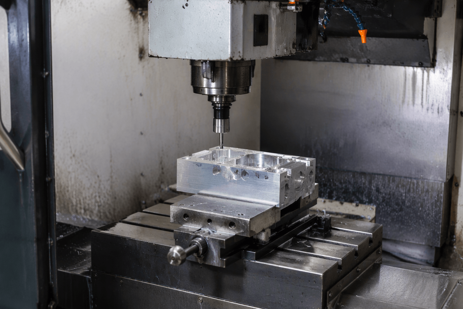
3 axis machining services use controlled movement along the X, Y, and Z axes to mill, drill, pocket, profile, and contour a secured workpiece. They are a credible choice when the required features can be reached from one orientation or through controlled repositioning, provided the supplier verifies the usable work envelope, setup strategy, material, tolerances, inspection scope, quantity, and schedule against the specific drawing.
A part does not become unsuitable for 3-axis milling merely because it has curves or detailed pockets. The more important question is whether the cutting tool can reach each feature at a workable angle without interference from the spindle, holder, fixture, or part itself. Buyers should therefore evaluate feature direction and access before comparing general claims about precision, speed, or cost.
When Does a Part Suit 3-Axis Machining?
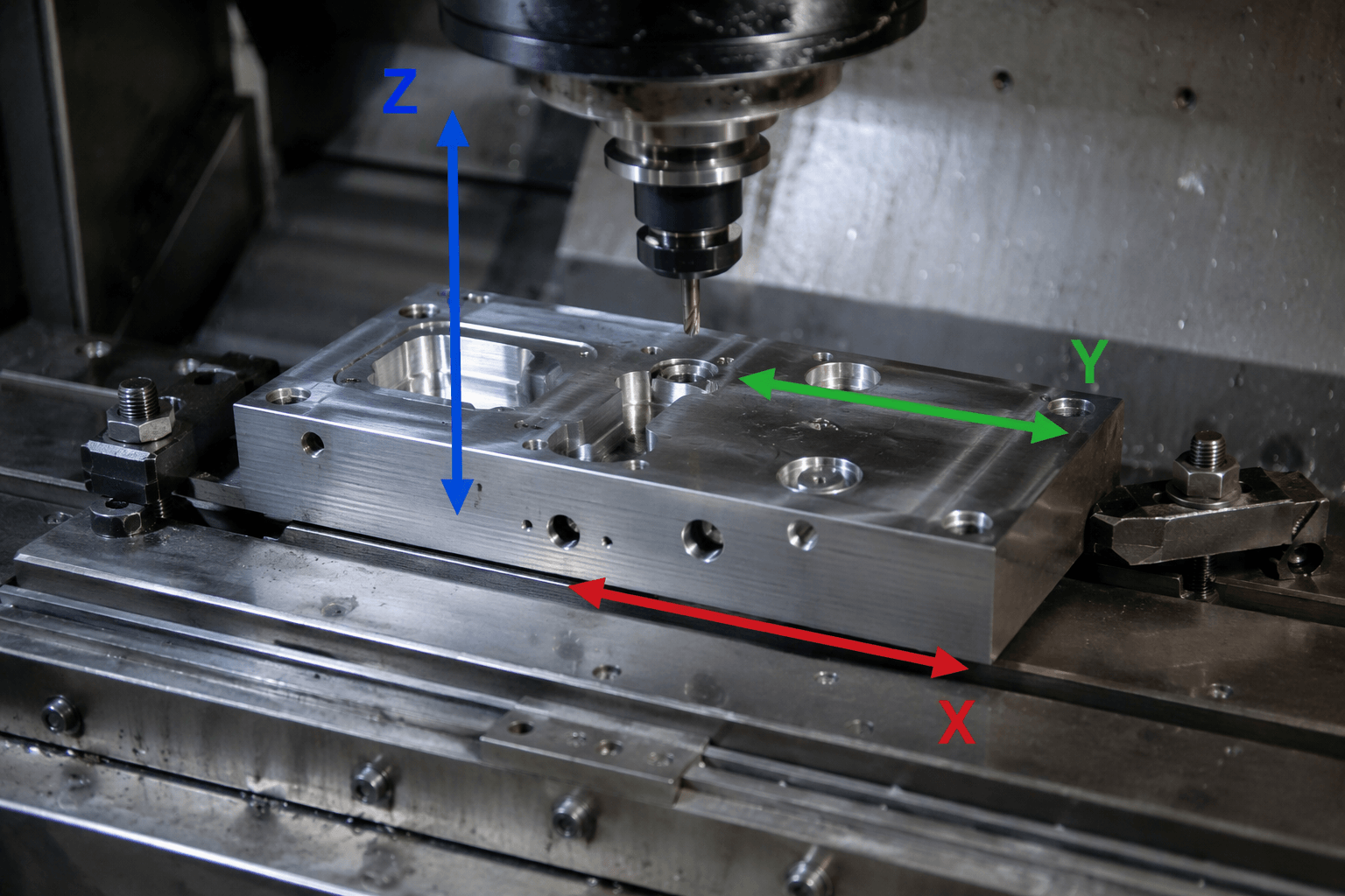
Standard 3-axis milling moves the cutting tool relative to a workpiece along three linear directions: X for side-to-side travel, Y for front-to-back travel, and Z for vertical movement. During a machining operation, the workpiece remains fixed in its clamped orientation. The machine does not automatically rotate or tilt it to expose another face.
This arrangement commonly fits prismatic parts with accessible top-facing features, such as plates, brackets, blocks, housings, mounting components, and fixture elements. Typical operations can include drilling, face milling, profiling, slotting, pocketing, chamfering, and machining freeform surfaces that remain reachable from the selected direction.
Part fit depends on more than overall shape. A rectangular component may still require several setups if it has critical bores on opposite sides. Conversely, a visually complex component may remain suitable for one setup if all important surfaces are accessible from above and the selected tools can reach them without excessive overhang.
Predominantly rotational parts may be better suited to CNC turning, which is a separate process rather than a form of 3-axis milling. The appropriate route should be determined from the part geometry and required features.
Standard 3-Axis, 3D Contouring, and 3+2 Machining Compared
Toolpath complexity and machine-axis configuration are not the same thing. A standard 3-axis machine can follow continuously changing X, Y, and Z coordinates to create contoured surfaces, but this does not add physical rotary axes. Indexed 3+2 machining uses rotary movement to position the workpiece or tool at a selected angle and then locks that orientation while three-axis cutting proceeds.
| Configuration | Movement during cutting | Feature-access fit | Point to verify |
|---|---|---|---|
| Single-orientation 3-axis | Linear X, Y, and Z movement with the part fixed | Top-facing holes, pockets, profiles, and reachable contours | Whether tools and holders can reach every required feature |
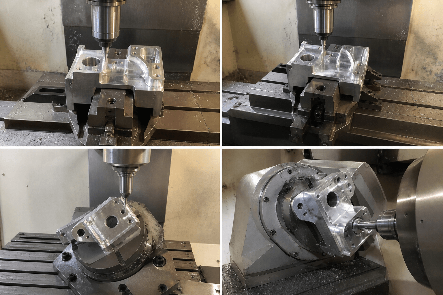
| Repositioned 3-axis | Three-axis cutting after the operator reclamps or relocates the part | Features on several faces that can be handled in separate setups | How critical relationships are maintained between setups |
| 3D contour milling | Simultaneous X, Y, and Z linear movement on a fixed part | Reachable curved, drafted, or freeform surfaces | Tool access, cutter geometry, step-over, and finish requirements |
| Indexed 3+2 | Rotary axes position and lock the part or tool before three-axis cutting | Angled faces and multi-side features that benefit from indexed access | Whether indexing reduces reclamping or improves access to critical features |
| Simultaneous multi-axis | Linear and rotary axes move together while cutting | Features requiring changing tool orientation, deep side access, or coordinated rotary motion | Whether continuous rotary movement is genuinely required by the geometry |
This comparison is a process-fit guide, not a ranking. Repositioned 3-axis machining may be practical for one drawing, while indexed or simultaneous machining may provide a more controllable route for another. The supplier should explain the proposed method in relation to actual features rather than treating geometric complexity as a single category.
Translate Drawing Features Into Access and Setup Requirements
Begin by assigning every machined feature a direction. A pocket opening toward the top may be accessible in the first setup. A cross-hole through a side wall requires another orientation unless suitable indexed movement is available. A reverse-facing recess or true undercut may need special tooling, an alternative setup, or a different machining configuration.
Consider a hypothetical housing with a top cavity, mounting holes on two side faces, and a bore whose location must remain closely related to the cavity. The cavity and top holes may be completed in one orientation. The side holes require repositioning, while the bore-to-cavity relationship makes repeatable location between setups important. A supplier response should identify the datum scheme, expected orientations, and how the part will be relocated.
Workholding also consumes space and can block features. Vise jaws, clamps, fixture plates, and supporting elements must hold the workpiece rigidly while leaving the cutting area accessible. Thin walls, deep pockets, long tools, and interrupted cuts may affect fixture design or operation sequence. These conditions do not automatically disqualify 3-axis machining, but they need review before the setup and quotation can be considered reliable.
Drawing review should also distinguish dimensional complexity from access complexity. Numerous holes on one plane may require substantial programming and machining time without needing additional axes. A single angled bore, by contrast, may change the required equipment or setup approach.
Capability Evidence to Request From a Provider
A machine’s published X, Y, and Z travel does not by itself establish the maximum machinable part size. Fixtures, clamps, tool length, spindle clearance, rotary equipment, probing space, and safe approach distances reduce the usable work envelope. Ask the provider to confirm both nominal travel and the practical envelope available for the proposed setup.
The capability review should cover the following evidence:
- Part dimensions and weight: Confirm the complete stock and finished dimensions, not only the cutting area. Request the supported part size and weight for the proposed machine and fixture arrangement.
- Geometry and setup: Ask for the planned orientations, estimated setup count, datum approach, and any custom workholding needed to expose or stabilize the features.
- Material: Provide the exact grade, condition, and any governing material specification. Material family alone may be insufficient because machinability and stock condition can affect the production method.
- Tolerances: Identify critical dimensions, geometric controls, datum references, and relationships that cross setup boundaries. Any tolerance or repeatability statement should be tied to the part, process plan, and inspection method.
- Surface requirements: Separate dimensional surface-finish callouts from cosmetic expectations and post-machining treatments. Curved surfaces may require a defined toolpath strategy and step-over based on the specified result.
- Machine and tooling fit: Request relevant machine type, spindle, holder, cutter, reach, and clearance information where these factors affect feasibility. Evidence should be specific to the job rather than a general equipment list.
- Inspection: Define which characteristics require measurement, the reporting format, sampling expectations, material documentation, and any traceability requirements.
- Volume and scheduling: State prototype or production quantity, repeat-order expectations, requested delivery timing, and whether releases will be scheduled. The provider should confirm current capacity and timing rather than relying on a generic lead-time claim.
Compare Quotations on the Same Technical Basis
Different prices may reflect different interpretations rather than different efficiency. Before comparing totals, confirm that each provider used the same drawing revision, material specification, stock assumptions, quantity, tolerance requirements, surface finish, inspection scope, packaging needs, and requested timing.
Then compare the proposed manufacturing route. One supplier may plan three manual setups on a 3-axis machine, while another proposes indexed 3+2 machining. Review how each approach controls critical feature relationships, where reclamping occurs, what fixture is required, and which dimensions will be inspected after each operation. A lower setup count is not automatically the better plan if access, rigidity, or verification remains unresolved.
Secondary operations should be shown separately. Machining time, outside finishing, assembly, inspection documentation, and logistics can have different scheduling dependencies. This distinction helps procurement teams compare scope and identify whether delivery estimates include every required stage.
For a technical manufacturability review, provide the part drawing or 3D model, material specification, order quantity and repeat-order expectation, critical tolerances, inspection requirements, required surface finish, applicable secondary operations, and requested delivery timing. Through its custom CNC machining inquiry pathway, Yishang can review whether the supplied geometry appears suitable for 3-axis machining and identify setup, access, or missing-specification questions that need clarification before pricing.
Frequently Asked Questions
Which part geometries are best suited to 3-axis machining services?
Parts are generally good candidates when their critical features are reachable along the X, Y, and Z directions from one orientation or from a manageable series of repeatable setups. Plates, blocks, brackets, housings, pockets, profiles, and top-accessible hole patterns are common geometry types, but suitability must be confirmed from the complete drawing, dimensions, fixture space, and tolerance relationships.
Can a 3-axis machine produce curved or contoured surfaces?
Yes. Coordinated X, Y, and Z toolpaths can produce reachable 3D contours while the workpiece remains fixed. The achievable result depends on surface geometry, cutter selection, tool reach, step-over, material, rigidity, and the specified finish. This capability does not turn the machine into a 3+2 or simultaneous multi-axis system because no rotary-axis movement has been added.
When does a part need 3+2 or simultaneous multi-axis machining instead?
Indexed 3+2 machining may be appropriate when angled or multi-side features benefit from positioning the workpiece or tool at fixed orientations. Simultaneous multi-axis machining may be required when the tool orientation must change continuously during cutting or when geometry cannot be reached through fixed orientations. The decision should follow feature-access and setup analysis, not part appearance alone.
What information is needed to confirm 3-axis service feasibility?
Supply a current drawing and preferably a 3D model, along with finished and stock dimensions, material grade and condition, quantity, critical tolerances, datum requirements, surface-finish specifications, inspection and reporting needs, secondary operations, repeat-order expectations, and requested delivery timing. These details allow the supplier to evaluate machine envelope, tooling access, workholding, setup count, measurement strategy, and production scheduling.