
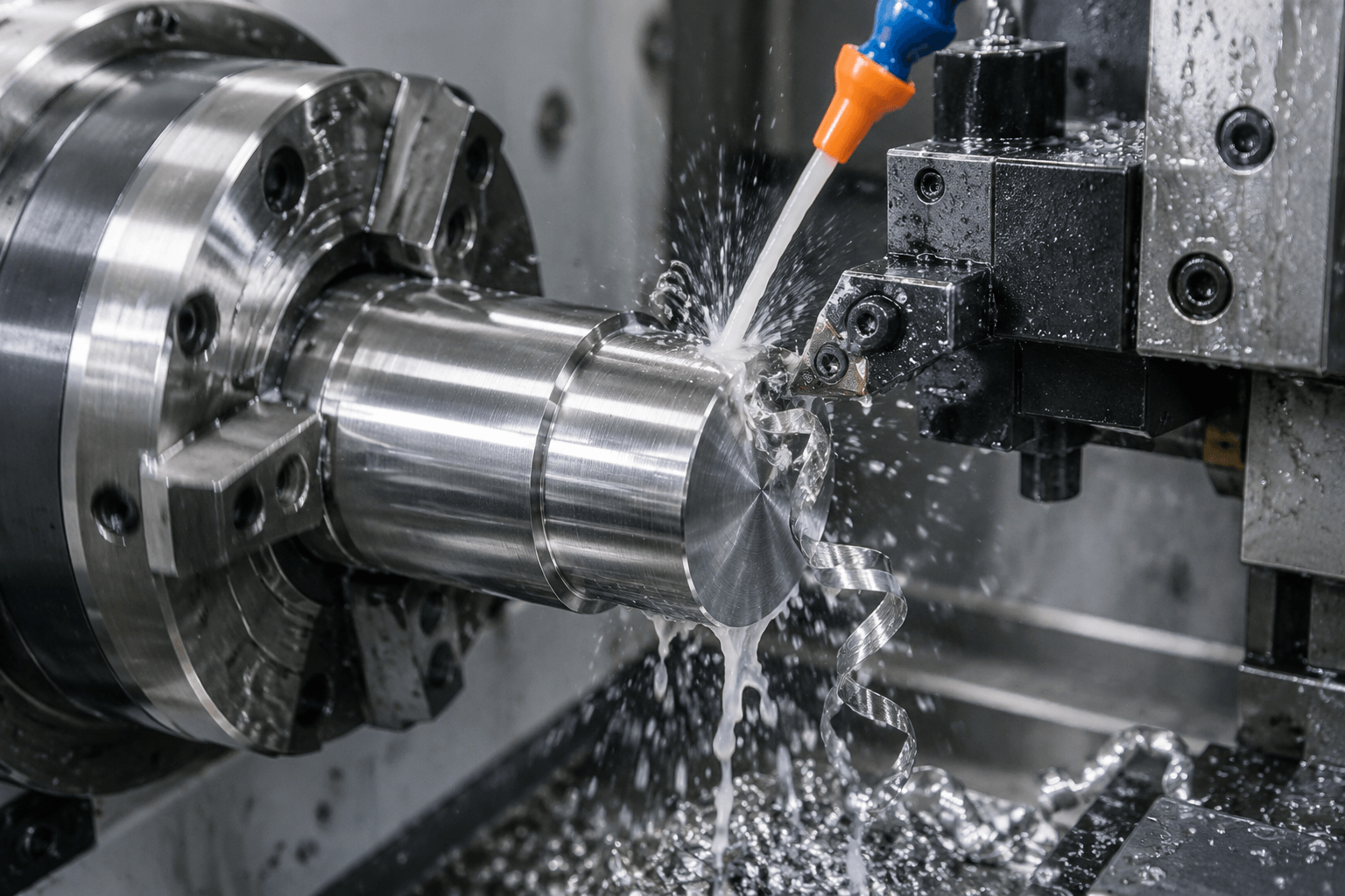
304 stainless steel is machinable, but it is not a free-machining stainless grade. Stable results depend on controlling work hardening, heat, chip formation, built-up edge, and tool engagement according to the specific operation, material condition, tooling, and setup.
This distinction matters because a parameter proven in turning does not automatically apply to milling, drilling, or tapping. Published speeds, feeds, and machinability ratings are useful only when their reference material, test method, tool, coolant condition, and workpiece condition are known.
What Makes 304 Stainless Difficult to Machine?
304 is an austenitic stainless steel selected widely for its corrosion resistance, formability, weldability, appearance, and general fabrication performance. Those advantages do not make it easy to cut. Compared with a free-machining grade, 304 demands closer control of the interaction between the cutting edge and the material.
Work hardening is one of the central issues. As 304 is plastically deformed, the affected material can become harder. A sharp tool taking a defined chip cuts beneath the previously affected surface. A worn tool, insufficient feed, excessive runout, or a pause in the cut may rub or burnish the surface instead. The next tool engagement then encounters a more difficult layer, increasing cutting forces and potentially accelerating wear.
Heat management presents another challenge. Heat concentrated near the cutting zone can soften or damage a cutting edge, encourage material adhesion, and make dimensional or finish control less consistent. Coolant must reach the active edge and chip interface; simply flooding the general area may not provide effective cooling or lubrication where it is needed.
304 also tends to produce ductile, continuous chips under many cutting conditions. Chips that do not break predictably can wrap around the workpiece or tool, obstruct coolant, mark a finished surface, and interfere with automatic production. Chipbreaker selection and feed must therefore work together with the depth of cut and operation geometry.
Built-up edge occurs when workpiece material adheres to the cutting edge. As that deposit grows and breaks away, it can change the effective tool geometry and pull material across the machined surface. The visible result may be a fluctuating finish, burr formation, dimensional variation, or premature edge failure. These are related symptoms, but they should not all be attributed to work hardening without checking tool condition, rigidity, chip evacuation, coolant delivery, and actual cutting engagement.
Turning, Milling, Drilling, and Tapping Behave Differently
The phrase 304 stainless machinability is too broad to define a single cutting response. Each operation loads the tool differently and creates its own risks.
Turning
Turning can provide relatively continuous engagement when the geometry permits. This helps maintain a consistent chip load and thermal condition, but long ductile chips may become a serious problem. Insert geometry must suit the feed and depth of cut so that the chipbreaker actually functions. Unnecessary dwell, repeated light passes, and a worn edge can rub the surface and make the following pass less stable. Interrupted turning, such as cutting across slots or cross-holes, adds impact and thermal cycling that continuous-turning data may not represent.
Milling
Milling is inherently interrupted because each tooth repeatedly enters and leaves the material. Cutter runout can cause one insert or flute to carry more load than the others, while weak fixturing may allow vibration at entry or exit. Engagement strategy matters: abrupt changes in radial engagement, repeated re-entry into hardened material, or feed reduction that becomes rubbing can shorten tool life and damage finish. A search for milling 304 stainless steel speeds and feeds should therefore lead to a tool-specific starting point, not a universal setting.
Drilling
Drilling combines restricted coolant access, difficult chip evacuation, and cutting-speed variation across the drill radius. Chips trapped in a deep or poorly cleared hole can generate additional heat and score the wall. A drill that stops advancing while continuing to rotate may rub and harden the material ahead of the cutting edge. Pecking can help chip evacuation in some situations, but an unsuitable peck cycle may introduce repeated rubbing or inefficient re-entry. Hole depth, diameter, drill design, coolant route, and machine capability all affect the appropriate strategy.
Tapping
Tapping is especially sensitive because several teeth engage an already machined hole, and there is limited room for chips. The drilled-hole size, chamfer, alignment, lubricant delivery, tap geometry, thread depth, and blind-versus-through-hole condition all matter. A work-hardened hole or trapped chip can raise torque rapidly. Thread milling or forming taps may be considered for suitable parts, but neither is an automatic substitute: thread form, hole condition, material behavior, equipment, and specification must support the choice.
Sheet metal laser cutting, punching, and forming should be evaluated separately. They may use the same 304 grade, but they do not reproduce the chip-forming mechanics of CNC turning, milling, drilling, or tapping.
303 vs 304 vs 316: Machinability and Selection Tradeoffs
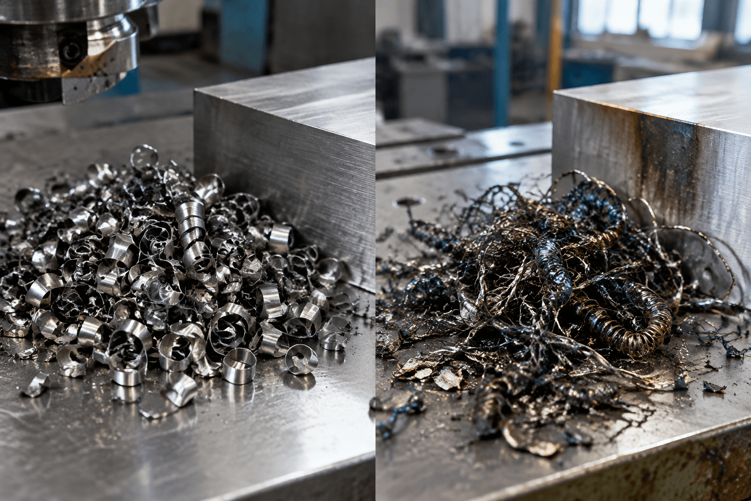
303 is generally easier to machine than 304 because additions intended to improve chip breaking and reduce cutting difficulty support free-machining behavior. That advantage comes with tradeoffs. 303 is not automatically appropriate when the part requires the corrosion performance, welding response, forming behavior, or specification compliance associated with another grade.
Comparing 304 with 316 is less suitable for a simple ranking. Both are austenitic grades that can work harden and produce difficult chips. In many machining situations, 316 is treated as at least as demanding as 304, but the actual result depends on material condition, composition within specification limits, product form, operation, tooling, and test method. Grade choice should be driven first by part function and environment, followed by a manufacturing plan appropriate to that grade.
| Grade | Relative machining behavior | Broader selection considerations | When it may fit |
|---|---|---|---|
| 303 | Usually the easiest of these three to machine; generally supports better chip breaking. | Its free-machining composition can limit corrosion resistance, welding suitability, and some fabrication options compared with 304. | Machined components where productivity is important and the drawing, environment, and downstream processes permit 303. |
| 304 | Machinable with controlled engagement, sharp tooling, effective cooling, and chip management; not free-machining. | Offers a widely used balance of corrosion resistance, forming, welding, finish, and availability. | Parts needing the broader fabrication characteristics of 304 as well as machined features. |
| 316 | Often comparable to or more demanding than 304 in chip-forming operations; conditions prevent a universal ranking. | Commonly considered where the service environment requires corrosion performance beyond what 304 provides. | Parts for which the specified exposure and functional requirements justify 316, despite possible machining penalties. |
A stainless steel machinability chart can support preliminary comparison, but its numbers should not be detached from their basis. A meaningful rating identifies the reference material, machining operation, tool material and geometry, failure criterion, workpiece condition, coolant arrangement, and test procedure. Ratings from different sources may not be directly comparable.
Process Controls for Repeatable 304 Machining
Successful machining starts by confirming what material is actually being cut. Annealed bar, cold-worked stock, plate, cast material, and previously formed features may not respond identically. Material specification, product form, hardness or condition where relevant, grain direction in wrought products, and prior processing can influence cutting forces and consistency.
- Protect the cutting action. Use a sharp edge and geometry intended for austenitic stainless steel and the actual operation. The tool must cut rather than dwell, skid, or repeatedly rub a hardened surface. Tool material, coating, edge preparation, chipbreaker, and toolholder should be considered as a system.
- Maintain meaningful chip thickness. Very light engagement is not inherently safer. Feed, depth of cut, radial engagement, entry method, and tool runout determine whether the edge forms a chip or mostly rubs. Finishing passes still need a stable cutting action.
- Keep the setup rigid. Minimize unsupported workpiece length and tool overhang where geometry allows. Check workholding, spindle condition, holder accuracy, insert seating, and runout. Deflection or vibration can vary chip load and leave chatter, taper, or inconsistent finish.
- Deliver coolant to the active zone. Coolant concentration, pressure, flow, nozzle position, filtration, and through-tool capability may all affect heat removal and chip evacuation. The best arrangement differs between an external turning tool, a deep drill, and an enclosed milling pocket.
- Plan engagement and re-entry. Continuous, stable cutting is useful where the operation allows it. Milling remains interrupted by nature, so toolpaths should manage entry, exit, corner engagement, and recutting of chips. In drilling and tapping, avoid dwell and ensure that evacuation cycles do not create repeated rubbing.
- Monitor wear before output drifts. Inspect the edge for adhesion, chipping, flank wear, and abnormal chip formation. Connect those observations to dimensional checks and surface-finish requirements. Replacing or indexing a tool should be based on the part’s acceptance criteria and a validated process, not an unsupported universal tool-life figure.
Speeds and feeds should come from tool-manufacturer guidance and then be validated under defined shop conditions. Useful records identify the grade and material condition, operation, tool and diameter, engagement, coolant method, holder and setup, measured wear criterion, dimensional result, and required surface finish. This also makes prototype-to-batch adjustments more defensible.
Machining difficulty can affect cycle time, tooling consumption, inspection frequency, and scheduling, but it does not establish part cost by itself. Geometry, tolerance, surface-finish specification, quantity, stock form, number of setups, and downstream finishing or assembly remain important.
Frequently Asked Questions
Is 304 stainless steel free-machining?
No. 304 can be machined successfully, but it is not a free-machining stainless grade. It tends to work harden, concentrate heat near the cutting zone, and form ductile chips, so tooling, engagement, rigidity, coolant delivery, and chip control require attention.
Why does 304 work harden during machining?
304 strain-hardens as its surface is plastically deformed. A cutting edge that rubs because of wear, low chip thickness, deflection, runout, or dwell can harden the affected layer instead of removing it cleanly. The next engagement then meets material that may impose greater load on the tool.
Is 304 or 316 harder to machine?
316 is often treated as comparable to or more demanding than 304, but there is no valid universal answer without test conditions. Product form, material condition, operation, geometry, tool, coolant, and measurement criterion can change the result. Corrosion and part-function requirements should decide whether 304 or 316 is suitable before machining is optimized.
Can one speeds-and-feeds chart apply to every 304 stainless job?
No. A chart is a starting reference only when it matches the operation, tool type and diameter, material condition, engagement, coolant method, and machine setup. Turning data should not be applied automatically to milling, drilling, or tapping.