
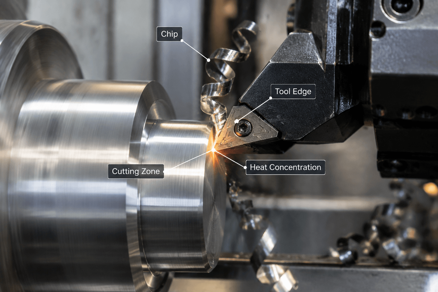
316 stainless steel is generally challenging to machine because it is tough, generates substantial cutting forces and heat, forms ductile chips, and work-hardens readily. It can still be machined reliably, but speeds and feeds must be matched to the material condition, operation, tool, engagement, machine rigidity, coolant delivery, and required outcome rather than copied from a generic chart.
What 316 Machinability Means in Practice
Machinability is not a single material property. It describes how a material behaves under defined cutting conditions, often judged through tool life, cutting force, chip control, surface finish, burr formation, dimensional stability, or material-removal rate. A rating from one test cannot automatically predict another operation performed with different tooling and equipment.
316 is an austenitic stainless steel. Its strength and toughness allow the material ahead of the cutting edge to resist deformation, increasing cutting forces compared with many readily machinable steels. Its ductility can produce long, continuous chips that interfere with the tool, workpiece, or coolant flow. Heat is concentrated around the tool-chip interface, while repeated deformation can harden the surface being cut.
Work hardening is especially important. If a worn or poorly presented edge rubs instead of shearing, the next cutting edge may encounter a harder layer. Light passes are therefore not automatically gentle: an excessively small feed or depth of cut can promote rubbing, heat, rapid wear, and inconsistent dimensions. Conversely, increasing engagement without considering tool strength, spindle load, and rigidity can overload the edge.
The practical objective is a stable shearing action with controlled chips and sufficient heat removal. Tool wear should be monitored by wear pattern rather than by elapsed time alone. Useful observations include flank wear, edge chipping, built-up material, chip color and shape, burr size, surface texture, spindle load, and dimensional movement as production continues.
The Grade Name Does Not Define the Whole Workpiece
A drawing that says only “316 stainless steel” leaves several variables unresolved. These variables can explain why a prototype, replacement batch, and production run do not behave identically even though their nominal grade is unchanged.
- 316 versus 316L: 316L has a lower maximum carbon requirement than 316. This distinction is important for corrosion and welding considerations, but it does not guarantee a fixed machining difference. Their machining behavior can overlap, and condition or product history may have more influence in a particular setup.
- Material condition: Annealed material and material containing prior cold work do not present the same hardness, strength, or residual stress. A cold-worked region may increase cutting load and wear or move after stock is removed.
- Product form: Bar, plate, tube, forged stock, and other forms follow different processing routes. Grain flow, straightness, surface condition, dimensional variation, and available machining allowance can therefore differ.
- Fabrication history: Rolling, drawing, bending, straightening, welding, and thermal exposure can create local differences. A machined feature crossing a formed or heat-affected region may not behave like one located in uniform base material.
- Microstructure and composition control: Grain structure, inclusions, and permitted chemistry variation can influence chip formation and tool interaction. Free-machining behavior should not be assumed unless the specified material was deliberately produced for it.
Traceability should therefore include the exact designation, condition, product specification, and relevant fabrication state. When a machined interface is added to a formed or welded component, machining and sheet metal fabrication remain separate processes. Guidance for cutting a bore or face does not automatically apply to bending, welding, finishing, or assembly.
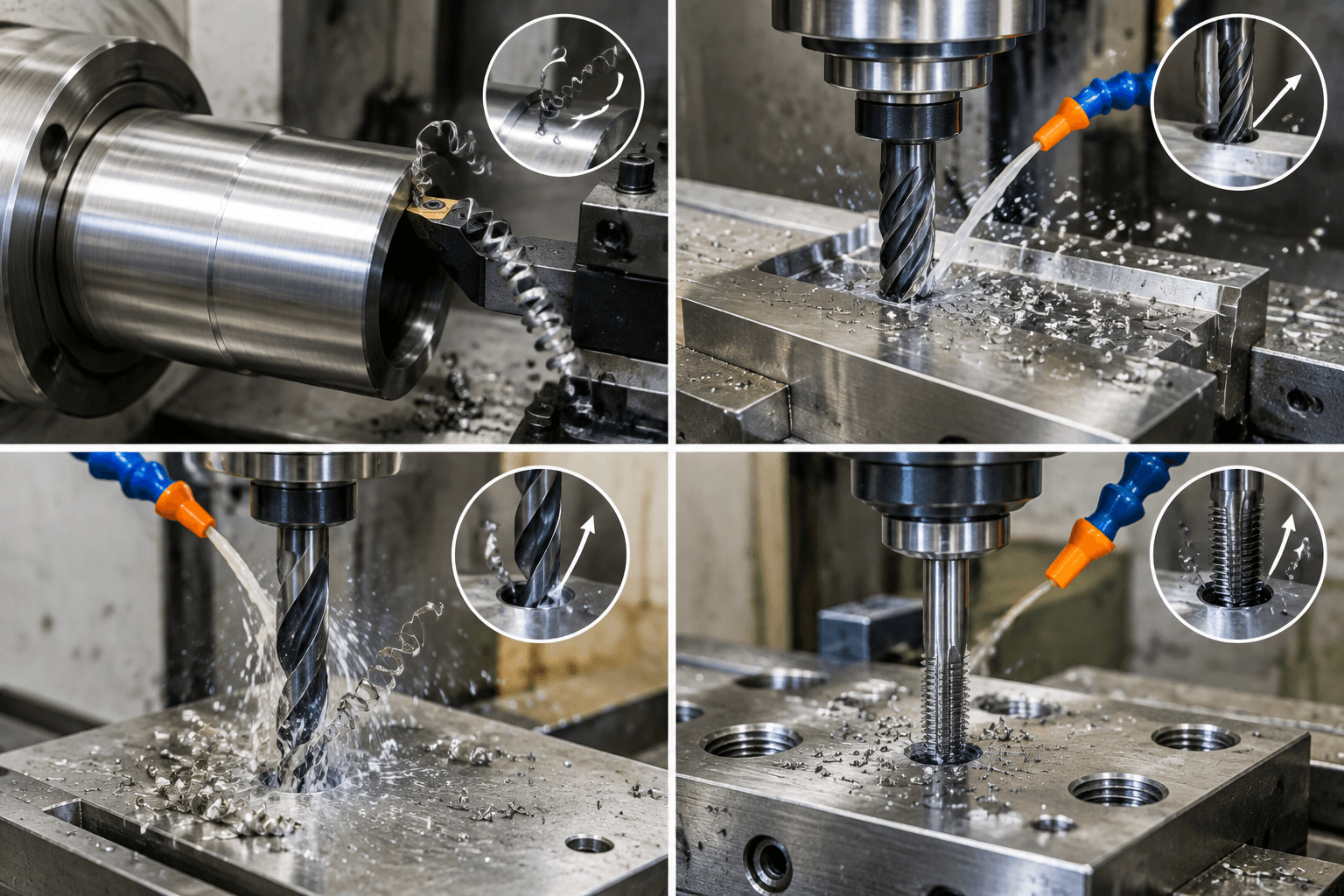
Turning, Milling, Drilling, and Tapping Present Different Risks
The same grade can require different strategies because tool engagement and chip evacuation change by operation. Readers evaluating a defined component can review the broader custom CNC machining process, but the operation-specific issues below should still be resolved.
Turning
Turning usually produces continuous engagement, concentrating heat at the insert and making chip control central to process stability. A sharp, supported edge and chipbreaker suited to the feed, depth of cut, and material can help prevent long chips from wrapping around the workpiece. Constant-surface-speed control may compensate for changing diameter, but spindle limits, workholding, part balance, and reduced rigidity on slender sections must be considered.
Very shallow finishing passes can encounter a work-hardened surface left by an earlier cut. Roughing and finishing allowances should be planned so the finishing edge removes material rather than rubbing across it. Insert geometry, nose radius, tool overhang, coolant direction, and workpiece support also affect chatter, deflection, finish, and size.
Milling
Milling is an interrupted process. Each tooth repeatedly enters and exits the work, so thermal cycling and entry impact can cause chipping if the tool grade or entry strategy is unsuitable. Cutter runout may leave one flute carrying a disproportionate load. Stable workholding, short overhang, controlled radial engagement, and a toolpath that avoids unnecessary dwelling are important.
Chip recutting can damage the edge and finished surface, particularly in pockets. Coolant or air delivery must clear chips effectively and suit the selected tool system. Arc or roll-in entry, climb milling where the machine and setup support it, and consistent engagement may reduce abrupt load changes, but each choice must be validated for the geometry.
Drilling
Drilling confines the cutting zone inside the hole, making heat and chip evacuation more difficult. A rigid setup, accurate entry, suitable point geometry, and coolant reaching the cutting edges become increasingly important as depth grows. Pecking can aid chip removal in some holes, but repeated shallow pecks, dwelling, or rubbing on re-entry may harden the surface. The cycle should be chosen around hole depth, drill type, coolant access, and chip behavior rather than applied automatically.
Tapping
Tapping combines extensive contact with limited chip space, so a work-hardened hole or trapped chip can quickly raise torque. The drilled-hole size must comply with the drawing and thread acceptance requirements while providing an appropriate cutting allowance. Tap geometry, coating, lubrication, alignment, synchronization, and reversal behavior all matter. Cut taps, forming taps, and thread milling are not interchangeable solutions; material condition, wall thickness, thread depth, machine control, and inspection method determine which is suitable.
How to Read a 316 Stainless Steel Machinability Chart
A credible chart is a starting-point document for a defined tool and operation—not a universal recipe for 316. Before using its values, confirm whether it applies to turning, milling, drilling, or tapping and whether the stated material group covers the actual grade and condition.
The chart or tool-selection data should identify, where applicable:
- tool material, substrate, coating, edge preparation, and chipbreaker or flute geometry;
- tool or cutter diameter, number of effective teeth, and tool projection;
- roughing, semifinishing, finishing, slotting, peripheral milling, or another engagement type;
- cutting speed, feed per revolution or feed per tooth, and axial and radial depth of cut;
- coolant condition, including dry, flood, mist, or through-tool delivery where supported;
- workpiece hardness or condition and any material-group assumptions;
- stability adjustments for long overhangs, thin walls, interrupted cuts, or weak workholding.
In metric calculations, spindle speed is derived from cutting speed and effective diameter: n = (Vc × 1000) / (π × D). Turning or drilling feed rate can be calculated from feed per revolution: Vf = fn × n. Milling feed rate uses feed per tooth and the number of effective teeth: Vf = fz × z × n. These formulas convert selected inputs; they do not establish which inputs are safe.
Cutting speed, feed, and depth of cut must also be considered together. Lowering feed too far can cause rubbing, while raising speed may increase interface temperature. Increasing depth can move the edge beneath a hardened skin but also raises force and deflection. Start with the range published for the exact tool family, then make controlled adjustments based on wear, chips, load, finish, dimensions, and process stability. Record the complete setup so a successful trial can be reproduced.
316 Compared with 304 and Free-Machining 303
| Grade | General machining tendency | Important qualification |
|---|---|---|
| 303 | Usually the most machinable of these three because additions intended to improve machining promote chip breaking and reduce some cutting difficulties. | Its corrosion, forming, and welding characteristics differ from 304 and 316. It should not replace the specified grade solely to shorten machining time. |
| 304 | Challenging austenitic stainless steel that can work-harden and form ductile chips; it is often regarded as somewhat easier to machine than 316. | Actual results can overlap with 316 because condition, hardness, supplier route, tooling, and test method affect performance. |
| 316/316L | Generally demanding, with toughness, cutting heat, chip control, and work hardening requiring attention. | It is commonly selected when its corrosion-related properties are needed. 316 and 316L should not be assumed to machine identically in every condition. |
Accordingly, the answer to “Is 304 or 316 harder to machine?” is usually 316 under comparable conditions, but that is a qualified trend rather than a production guarantee. The answer to “Which stainless steel is most machinable?” also depends on the comparison set. Among 303, 304, and 316, free-machining 303 generally leads, but grade suitability must be decided from the service environment, fabrication route, mechanical requirements, and drawing—not machinability alone.
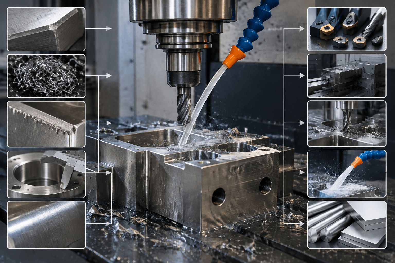
316 Machining Symptoms: What to Check Before Changing the Process
| Observed symptom | Variables to investigate | Corrective direction to test |
|---|---|---|
| Rapid flank wear or edge breakdown | Cutting speed, interface heat, coating suitability, hardened skin, runout, interrupted engagement, coolant access | Inspect the wear pattern; verify tool selection and reduce heat or impact without allowing the edge to rub. |
| Long or tangled chips | Feed and depth relative to chipbreaker range, edge geometry, tool path, coolant direction, material condition | Bring engagement into the toolmaker’s chip-control window and improve safe chip evacuation. |
| Heavy burrs | Edge sharpness, exit direction, tool support, feed, remaining wall thickness, material ductility | Review edge condition and exit strategy; consider supported geometry or a planned deburring operation. |
| Dimensions drift during a run | Progressive wear, thermal growth, workpiece stress, clamping distortion, tool deflection, measurement timing | Separate tool, machine, workholding, material, and inspection effects before applying offsets. |
| Poor or inconsistent surface finish | Built-up material, chatter, chip recutting, worn edge, runout, nose radius, unstable coolant delivery | Examine the surface pattern and tool edge, then correct rigidity, chip clearance, or parameter balance. |
| High drilling or tapping torque | Work-hardened hole, dull tool, hole size, alignment, chip packing, lubrication, excessive engagement | Stop before tool failure; verify the prepared hole, tool condition, synchronization, and chip path. |
No symptom has only one cause. Change one controlled variable at a time where practical, document the result, and confirm that the correction does not create a new problem elsewhere. Acceptance should be based on the drawing’s dimensional, thread, surface-finish, and inspection requirements rather than visual appearance alone.
Frequently Asked Questions
Does 316L machine differently from 316?
It can, but not in a fixed or universally predictable way. 316L has a lower maximum carbon requirement, while hardness, cold work, product form, microstructure, and supplier processing can have greater practical influence on a particular cut. The exact material condition should accompany any tooling or parameter recommendation.
How can work hardening be limited during drilling or tapping?
Use a sharp, suitable tool; maintain positive cutting rather than rubbing; provide adequate lubrication or coolant; and remove chips effectively. Avoid unnecessary dwelling and cycles that repeatedly contact the same surface without cutting. Check hole size, alignment, rigidity, and tool wear before simply reducing speed or feed.
Why do two 316 speeds-and-feeds charts give different values?
They may assume different carbide grades, coatings, tool diameters, edge geometries, coolant methods, material conditions, engagement levels, or tool-life criteria. One may list a broad material group while another addresses a specific operation. Compare the chart assumptions before comparing its numbers.
What information should be provided when requesting machined 316 parts?
Specify 316 or 316L, the applicable material and product specification, condition, product form, and relevant fabrication history. Supply the drawing and model, quantities, datum scheme, critical dimensions, thread requirements, surface-finish callouts, corrosion-related restrictions, and inspection or reporting expectations.