
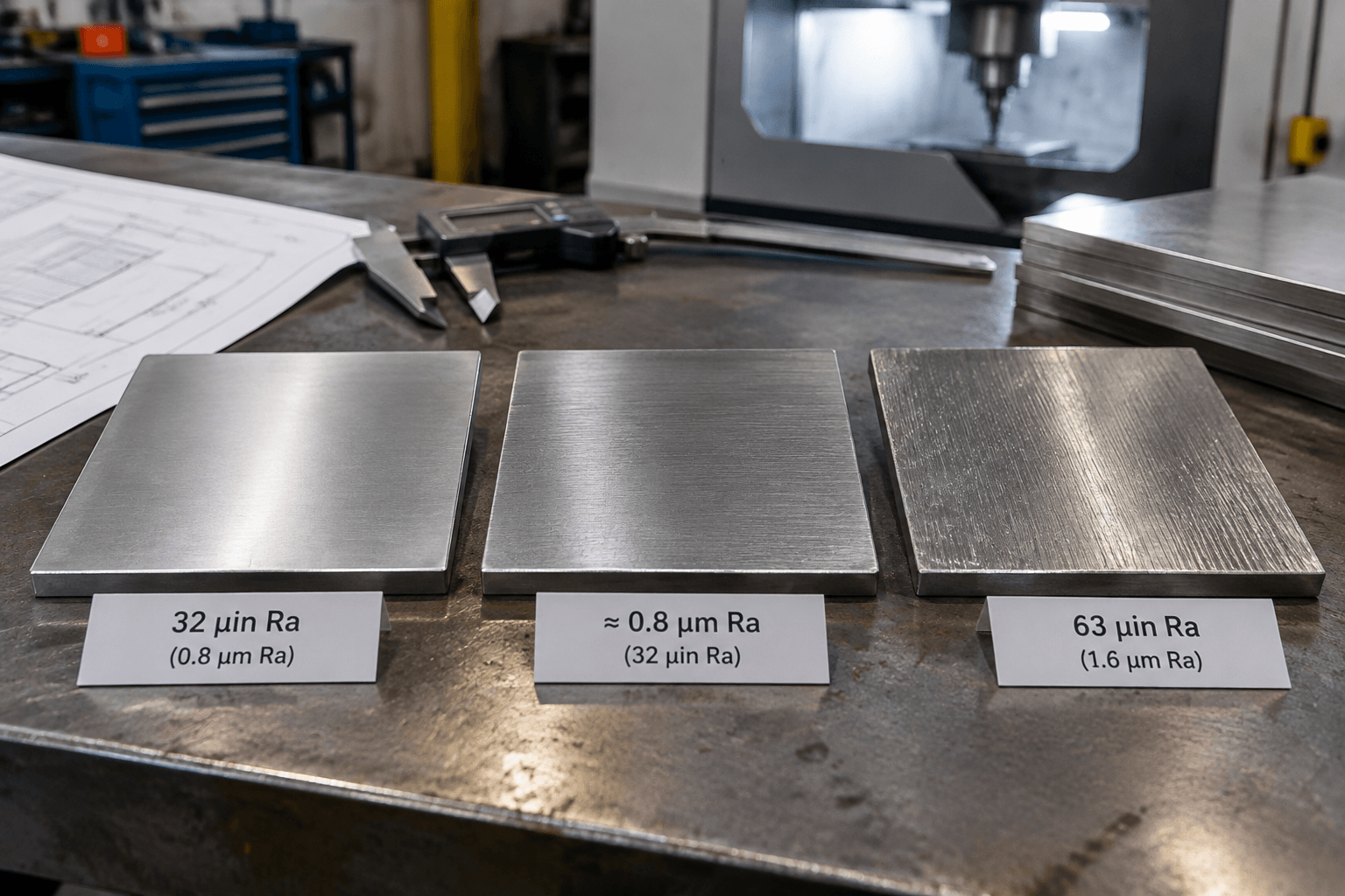
A 32 machine finish normally means 32 microinches Ra, which converts to 0.8128 micrometer Ra and is commonly rounded to 0.8 micrometer Ra. It does not mean 32 micrometers. The drawing must identify the parameter and units because the number 32 by itself can be misread.
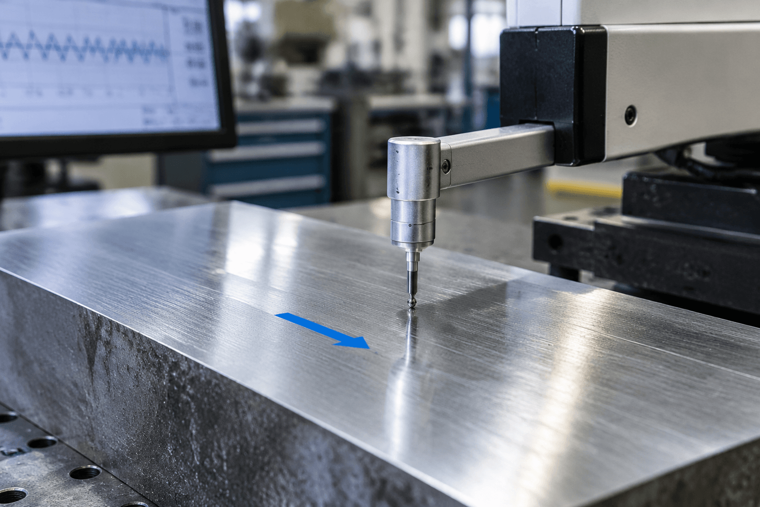
Even when the intended value is clear, inspection may not be. A stylus profilometer needs an accessible path of sufficient length, an appropriate measurement direction, and defined filtering and cutoff settings. A 32 Ra note on a broad milled face is therefore easier to interpret than the same note applied to a narrow land, curved diameter, interrupted slot, or edge-adjacent area.
Decode the 32 Machine Finish Callout
Ra is the arithmetic average roughness of a measured profile over the evaluation length after the applicable filtering has been applied. It expresses average profile deviation as a length value. When US customary units are used, surface roughness is often stated in microinches. Metric drawings commonly state Ra in micrometers.
| Notation | Interpretation | Equivalent value |
|---|---|---|
| 32 µin Ra | Thirty-two microinches arithmetic average roughness | 0.8128 µm Ra |
| 0.8 µm Ra | Metric value commonly associated with a 32 µin requirement after rounding | Approximately 31.5 µin Ra |
| 32 µm Ra | Thirty-two micrometers arithmetic average roughness | Approximately 1,260 µin Ra |
The conversion follows from one inch equaling 25,400 micrometers: 32 microinches multiplied by 0.0254 equals 0.8128 micrometer. This arithmetic does not decide how a drawing should be rounded or accepted. The stated units, drawing convention, applicable surface-texture standard, and acceptance rule remain controlling.
A bare “32” may be understood by people familiar with a particular drawing system, but it is not a complete international specification. The safer callout states Ra 32 µin or Ra 0.8 µm and identifies the governing drawing standard. That prevents the 1,000-fold unit error between microinches and micrometers.
32 Versus 63 Ra, Ra30, and Grade Labels
A 63 microinch Ra limit is approximately 1.6 micrometers Ra. Numerically, it permits about twice the average roughness of a 32 microinch Ra limit. That comparison does not mean every 32 Ra surface will look twice as smooth, reflect light in the same way, or perform twice as well. Tool path, lay, waviness, material response, and isolated defects can make surfaces with similar Ra readings appear or function differently.
| Callout | Approximate conversion | Specification note |
|---|---|---|
| 32 µin Ra | 0.8128 µm Ra | Commonly rounded to 0.8 µm, subject to the drawing convention |
| 63 µin Ra | 1.6002 µm Ra | Commonly rounded to 1.6 µm |
| Ra30 | Cannot be converted until units are known | Could mean 30 µin or 30 µm in different documentation contexts |
| N-grade label | Depends on the referenced grade system | Confirm the standard and numerical Ra value rather than inferring acceptance from the label alone |
Grade labels and numerical roughness values are not interchangeable without context. Some grade systems associate a nominal grade with a preferred metric Ra value, but that does not make an unsupported grade label the automatic equivalent of a 32 microinch requirement. In particular, a drawing reviewer should not substitute “N8” for 32 µin Ra. The controlling standard and the value shown on the drawing determine the requirement.
Likewise, “Ra30” is incomplete unless the drawing establishes units. Thirty microinches is close to, but not identical to, 32 microinches. Thirty micrometers is dramatically rougher. A supplier or inspector should request clarification rather than choose the interpretation that seems customary.
What a 32 Ra Number Controls
A 32 Ra callout controls the specified arithmetic average roughness limit under the applicable measurement rules. By itself, it does not fully define the surface or guarantee performance.
- Lay: Turning, milling, and grinding can leave different directional patterns at similar Ra values. If direction matters to sealing, sliding, lubrication, or appearance, the drawing must control lay separately.
- Waviness: Longer-spaced profile variation is distinct from roughness. Ra alone does not impose a waviness limit.
- Appearance: Gloss, color, reflectivity, tool marks, scratches, and visual uniformity are not completely described by an Ra value.
- Form and size: Surface texture does not replace dimensional, flatness, roundness, cylindricity, or other geometric requirements.
- Isolated features: A local pit, burr, tear, or scratch may be functionally unacceptable even when an averaged trace produces an acceptable Ra result. Such defects need separate criteria when relevant.
- Later processing: Polishing, blasting, coating, cleaning, handling, or assembly can change the final surface. The drawing should identify the production stage at which the requirement applies.
For a sealing face, Ra may be only one part of the requirement because lay and isolated leakage paths can matter. A sliding surface may also need controls related to direction or profile behavior. A cosmetic panel can meet Ra while showing visible directional variation. These examples do not establish universal additional limits; they show why the part’s function must determine whether Ra alone is sufficient.
Measure Where the Part Can Be Evaluated Reliably
Measurement direction is important because a stylus trace taken parallel to machining lay can produce a different result from one taken across it. Roughness is generally evaluated across the predominant lay when that direction is accessible and consistent with the governing method. If the required direction cannot be achieved, the drawing or inspection plan should define the alternative instead of leaving inspectors to choose independently.
Cutoff, filter, evaluation length, probe characteristics, and instrument setup affect the reported result. These settings should follow the applicable standard and be suitable for the expected profile. A short available trace may prevent the selected cutoff and evaluation length from being used correctly. Changing settings merely to fit a narrow feature can produce a result that is not directly comparable with a measurement made under the intended conditions.
Flat and Accessible Surfaces
A broad face usually provides several possible traces. The inspection plan should identify the controlled region, measurement direction, and number or distribution of locations. On a milled plate, for example, one center trace may miss roughness near tool entry, overlap bands, or an outer pass. Sampling should reflect the areas relevant to function without implying that a few traces characterize every point on the surface.
Curved or Cylindrical Surfaces
Curvature can affect probe contact, instrument alignment, and the profile presented to the stylus. The available axial or circumferential direction may also conflict with the preferred direction across the lay. The inspection method should state the trace direction and any fixture or curvature treatment required by the selected instrument and standard.
Narrow Lands and Edge-Adjacent Areas
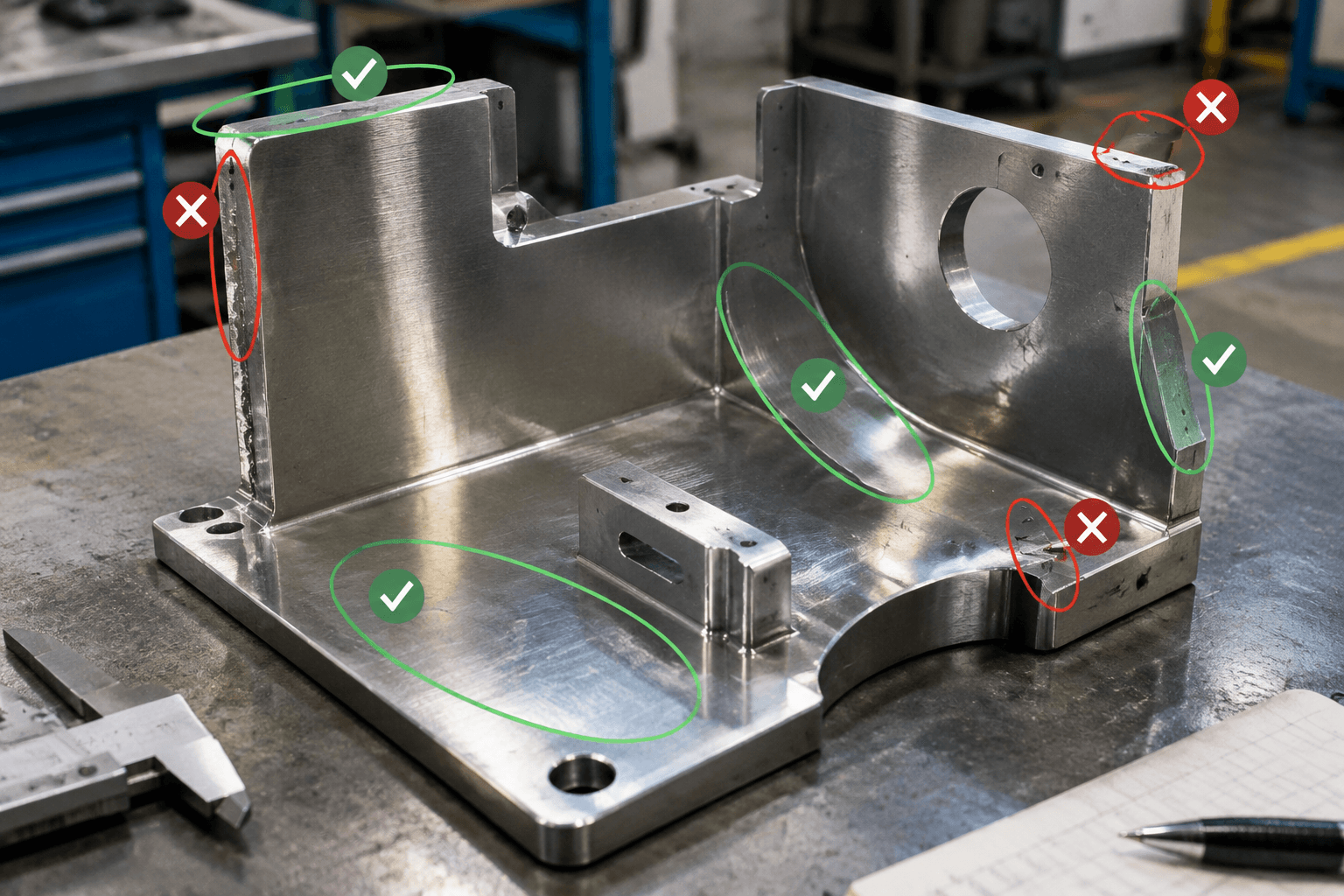
A land may be too short or narrow for the required traverse. Starting or ending a trace too close to an edge can introduce stylus transition effects or leave insufficient evaluation length. Before issuing the drawing, confirm that a physical probe can reach the identified area and complete a valid trace. If it cannot, revise the surface requirement, feature design, or agreed measurement method rather than accepting an improvised reading.
Interrupted and Nonuniform Surfaces
Holes, slots, grooves, keyways, pores, and repeated interruptions can cause the stylus to leave the intended profile or introduce data that the filtering method was not selected to handle. A surface with intentionally different regions also should not be represented by an unspecified average location. Identify included and excluded zones, and define how traces crossing interruptions are treated under the agreed method.
Anatomy of a Measurable 32 Ra Surface Requirement
A complete requirement combines the value with information that allows production and inspection to reproduce the same interpretation. The following is a field-by-field specification model, not a universal drawing note:
- Parameter and value: State Ra and the limit, such as Ra 32 µin or Ra 0.8 µm. Do not rely on “32 finish” alone.
- Applicable standard: Identify the surface-texture and drawing-symbol standard, including the revision when required by the organization’s document controls.
- Controlled surface: Attach the symbol to the exact face or identify the bounded region. State whether edges, transition radii, holes, interrupted areas, or post-process zones are excluded.
- Production stage: Clarify whether the value applies after machining, after a finishing operation, before coating, or on the delivered part.
- Measurement direction: Define direction relative to the lay or a part datum where function or geometry makes direction significant.
- Measurement settings: Establish the cutoff, filter, evaluation length, and other method details through the governing standard or an inspection instruction.
- Sampling locations: Identify required zones or a documented method for selecting locations, especially when the surface is large or nonuniform.
- Acceptance rule: State how individual traces, repeated measurements, and local nonconformities are evaluated. Do not assume every standard or organization applies the same rule.
- Evidence: Define whether the record must include measured values, location identifiers, direction, instrument or method identification, settings, date, and part or lot traceability.
Consider a machined cover with a wide sealing face, a narrow perimeter land, and several bolt-hole interruptions. Applying one 32 Ra symbol to the entire face leaves practical questions: whether traces may cross holes, whether the narrow land is included, where measurements are taken, and which direction is required. Marking the controlled sealing region and documenting valid trace locations resolves those questions without changing the roughness value.
A second example is a turned shaft with multiple diameters. A general 32 Ra note may be unnecessary or impossible to verify on short shoulders and reliefs. Applying the requirement only to the functional bearing diameter, with an accessible trace direction and defined inspection location, creates a requirement tied to the intended surface rather than every machined feature.
Build a Repeatable Acceptance Record
An inspection report should allow another qualified person to understand what was measured and under what conditions. At minimum, record the specified parameter and units, part and drawing revision, measured surface or location, result, and acceptance status. Where they influence interpretation, also record trace direction, cutoff and filter settings, evaluation length, instrument or method, and any approved deviation from the normal setup.
Visual inspection and comparator plates can support process checks or help locate suspect areas, but they do not independently verify a numerical 32 Ra requirement. Comparator use depends on matching process appearance, lay, lighting, viewing technique, and the agreed inspection method. Numerical acceptance requires a suitable measurement method unless the drawing or contract expressly establishes another approach.
Before finalizing requirements for machining parts with drawing-defined surface requirements, review the drawing revision, material, geometry, controlled surfaces, standard, units, and required reporting method together. This review should confirm that each specified area is physically measurable and that production and incoming inspection will apply the same acceptance logic.
Where RFQ Assumptions Create Cost and Production Risk
Many sheet metal fabrication problems begin before production starts. If drawings, tolerances, finish expectations, material grades, or assembly requirements are unclear, suppliers may quote based on different assumptions. That can make prices difficult to compare and may lead to rework, cosmetic rejection, assembly misalignment, or production delays later.
For OEM buyers, the goal is not simply to request the lowest price. The goal is to make sure each supplier is quoting the same manufacturing reality. Before confirming an order, clarify which dimensions are fit-critical, which surfaces are cosmetic, whether prototypes must match batch-production conditions, and how finished parts will be inspected.
Frequently Asked Questions
What coating thickness details should buyers define before requesting a quote?
Buyers should define the functional requirement, drawing notes, critical dimensions, material or process expectations, and any inspection points related to coating thickness. This helps suppliers quote the same manufacturing scope instead of making different assumptions.
How can masking areas affect cost, fit, or lead time?
masking areas can change tooling, forming, welding, finishing, inspection, or rework requirements. If buyers do not clarify it early, two supplier quotes may look comparable while covering different production risks.
Why should powder coating be reviewed before prototype approval?
powder coating may look acceptable on a single sample but become harder to control during batch production. Buyers should confirm whether the prototype reflects the same process, finish, and inspection conditions expected for production.
What inspection points matter most for 32 machine finish projects?
Important inspection points usually include fit-critical dimensions, holes or mating areas, cosmetic surfaces, finish build-up, welded or formed features, and any dimensions that affect downstream assembly. These points should appear in the RFQ or drawing notes.
How can buyers reduce assembly clearance risk before batch production?
Buyers can reduce risk by clarifying drawings, locking key material and finish assumptions, defining inspection timing, approving a representative sample, and confirming which dimensions or surfaces require tighter process control.
How can Yishang help review 32 machine finish requirements?
Yishang can review drawings, RFQ notes, material requirements, tolerance expectations, finish details, samples, and assembly needs to identify unclear assumptions before quoting or batch production.