
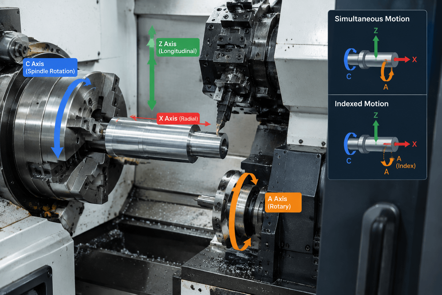
A 4 axis CNC lathe is a turning machine with four controllable motion axes, but the exact axis combination depends on its architecture. The term may refer to X, Z, Y, and C motion, two independently controlled tool slides, or another configuration; it does not automatically mean that all four axes can cut simultaneously.
What Does 4 Axis CNC Lathe Mean?
On a basic CNC lathe, the workpiece rotates in the spindle while the cutting tool moves along two primary linear axes:
- Z axis: movement parallel to the spindle centerline, normally controlling part length and axial profiles.
- X axis: movement toward or away from the centerline, normally controlling diameter.
Additional controlled motion can take several forms. A C axis may control the spindle’s angular position. A Y axis may move a live tool above or below the workpiece centerline. Alternatively, a machine with two tool slides may count X1, Z1, X2, and Z2 as four axes. Some architectures also incorporate a secondary spindle or other positioning axis.
- Z: tool travel along the workpiece axis
- X: tool travel across the workpiece radius or diameter
- C: controlled angular position of the spindle or workpiece
- Y or secondary linear axis: off-center tool movement or an independent tool slide
This distinction matters because axis count and coordinated-motion capability are different specifications. A fourth axis might only index the part to a fixed angle before cutting. Simultaneous motion means the control coordinates rotation and one or more linear axes continuously during the cut. Wrapped contours and helicoidal grooves generally depend on this coordinated behavior, whereas equally spaced cross-holes may require only indexed positioning.
How It Compares with Related CNC Machine Types
Machine categories overlap, and builders may use different naming conventions. Buyers should therefore compare the actual axis list, tooling, spindle control, and interpolation functions rather than selecting equipment by its label alone.
| Machine category | Typical arrangement | Rotary and milling capability | Suitable feature types |
|---|---|---|---|
| Conventional 3-axis turning setup | Often X and Z plus a third controlled axis, although definitions vary | May provide spindle positioning, a Y axis, or another function; live cutting is not guaranteed | Turned diameters, faces, tapers, grooves, threads, and configuration-dependent secondary details |
| 4-axis CNC lathe | Could be X/Z/Y/C, two X/Z tool slides, or another four-axis arrangement | May support indexing or simultaneous interpolation; powered tooling must be confirmed separately | Turned profiles and, when equipped appropriately, cross-holes, flats, off-axis details, and wrapped features |
| Live-tool lathe | A lathe with powered rotary tools | Can drill or mill without moving the part to a separate machine, but available directions depend on C, Y, turret, and control functions | Axial or radial holes, flats, slots, and selected milled details |
| Mill with a fourth axis | Three linear mill axes plus a rotary table or rotary fixture | The cutter rotates while the fixture indexes or continuously rotates the workpiece | Multi-sided parts, radial holes, wrapped engraving, flutes, and features requiring broad milling access |
| Mill-turn center | Integrated turning and milling architecture, potentially with multiple spindles and tool systems | Usually intended for more extensive combinations of turning and milling, subject to its specific configuration | Complex parts requiring multiple orientations, off-center machining, and setup consolidation |
A fourth-axis mill may be the better choice when milling access dominates, the part has substantial prismatic geometry, or the rotary feature must be approached from several directions. A lathe-based solution is often more natural when concentric turned surfaces establish the main geometry. A live-tool lathe and a 4-axis lathe can describe the same machine in some cases, but neither term proves the presence of Y-axis travel or simultaneous C-axis interpolation.
Features a Four-Axis Turning Configuration May Produce
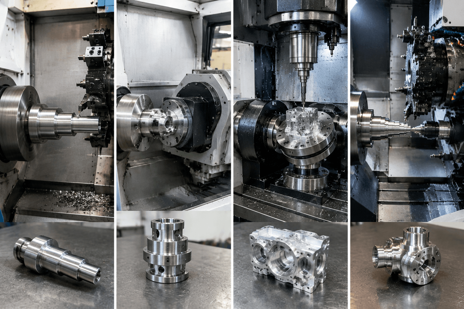
The machine becomes useful when a mostly rotational part also contains features that would otherwise require another setup. Feasible examples include:
- Cross-holes: radial holes produced after the spindle indexes to the required angular position. These require a powered drill or another suitable machining arrangement.
- Off-axis holes and slots: features displaced from the centerline, often requiring Y-axis movement as well as live tooling.
- Angular flats or repeated patterns: the C axis can position the workpiece at defined angles while a milling tool cuts each location.
- Wrapped geometry: text, channels, or profiles mapped around a cylindrical surface through coordinated rotary and linear movement.
- Helicoidal grooves: grooves generated by synchronizing workpiece rotation with axial feed. The required relationship depends on pitch, lead, groove form, and toolpath strategy.
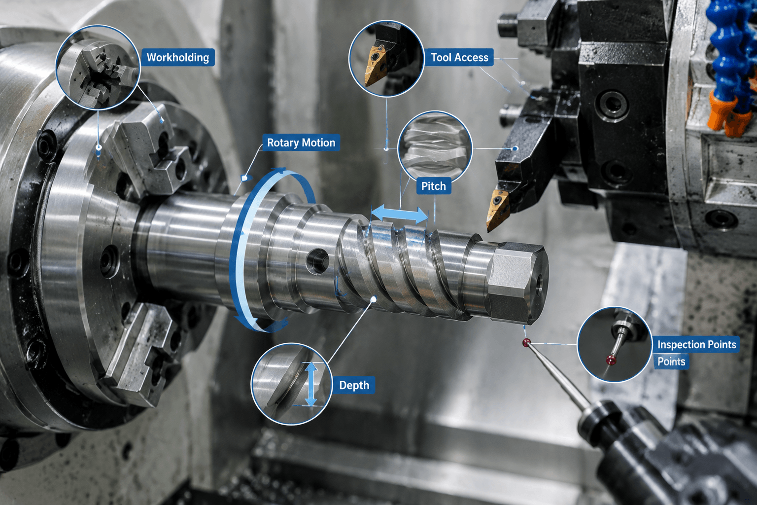
For a hypothetical cylindrical component with a spiral channel, rotating the workpiece slowly is not enough by itself. The machine control must coordinate angular position with Z-axis travel, and sometimes X-axis movement, while maintaining the intended pitch and depth. The post-processor must output motion the control can interpret correctly.
Feasibility also depends on diameter, unsupported length, wall thickness, feature depth, tool reach, material behavior, and tolerance relationships. A deep groove in a slender part can create deflection or vibration even when the programmed motion is available. Similarly, a tool may be unable to reach a feature near a chuck jaw or shoulder.
How to Verify 4-Axis Lathe Feasibility Before Programming
- Interpret the datums. Establish which turned diameter, face, or centerline controls the rotary and off-axis features. The coordinate system should preserve the drawing’s positional relationships.
- Confirm the machine architecture. Identify every usable axis, its travel, whether the spindle operates as a controllable C axis, and whether the required axes can interpolate together rather than only index.
- Plan workholding. Review grip length, jaw clearance, rigidity, runout influences, part distortion, and whether tailstock or other support is appropriate. Rechucking can affect concentricity between turned and milled details.
- Select tools and cutting directions. Check holder interference, tool projection, spindle orientation, cutting forces, and access to shoulders or recessed areas. Chip evacuation is especially important in deep cross-holes and narrow wrapped grooves.
- Verify synchronization and post-processing. A CAM toolpath is not sufficient unless the machine-specific post-processor and control support the commanded rotary and linear motion.
- Simulate the complete setup. Collision checking should include the chuck, jaws, turret, holders, workpiece, secondary spindle, and other machine elements represented in the setup.
- Define inspection methods. Pitch, angular position, groove depth, concentricity, and off-axis location may require different gauges or measurement strategies. Inspection access should be considered before machining begins.
These reviews apply to prototypes as well as repeat production. The difference is economic emphasis: a prototype may tolerate more flexible setup effort, while production often justifies dedicated workholding, optimized tools, and more formalized inspection. For broader process context, see custom CNC machining from first sample to repeat production.
4-Axis CNC Lathe Evaluation: Questions to Confirm Before Machining
A 4-axis arrangement is worth considering when it can maintain critical relationships between turned and secondary features, reduce rechucking, or combine operations efficiently. It is not automatically the lowest-cost route. A fourth-axis mill, conventional lathe followed by milling, or more integrated mill-turn process may fit the geometry better.
Capability questions
- Which four axes are being counted, and which can move simultaneously?
- Does the operation require continuous interpolation or only fixed-angle indexing?
- Are powered tools available in the required radial or axial orientation?
- Can the tool reach every feature without excessive projection or fixture interference?
- Can the workholding preserve the required concentricity and angular relationships?
- How will cross-features, groove pitch, surface condition, and positional tolerances be inspected?
Information needed for a meaningful process review
| Input | Why it matters |
|---|---|
| Part drawing and 3D model | Show datums, feature relationships, access restrictions, and complete geometry. |
| Material and heat-treatment condition | Affect cutting behavior, tool selection, distortion risk, and machining sequence. |
| Critical dimensions and tolerances | Determine workholding, setup, inspection, and whether operations should remain in one clamping. |
| Rotary, cross, off-axis, or helicoidal feature details | Define angular positions, pitch, lead, depth, orientation, and required coordinated motion. |
| Surface requirements | Help separate machined finishes from later grinding, coating, polishing, or other finishing operations. |
| Prototype and production quantities | Influence fixture investment, programming effort, tooling strategy, and cycle optimization. |
Cost is driven by the selected machine configuration, material, programming complexity, setup time, fixtures, cutting tools, tool wear, inspection, secondary operations, and quantity. Complex synchronization or difficult access may increase engineering effort even when the part is small. Conversely, combining several operations in one setup may reduce handling and alignment work at suitable volumes.
For a B2B OEM or ODM feasibility inquiry, submit the drawing or model together with material, heat treatment, critical tolerances, surface requirements, feature description, and quantity. Yishang supports B2B custom manufacturing projects and can use these inputs to review the appropriate CNC machining process route rather than assuming that any machine labeled “4-axis” is suitable.
Frequently Asked Questions
Is there such a thing as a 4-axis CNC lathe?
Yes, but the name is configuration-dependent. It may describe X, Z, Y, and C axes, two independently controlled tool slides, or another arrangement. Always request an axis diagram and clarification of indexed versus simultaneous motion.
Can a 4-axis CNC lathe machine a helicoidal groove or wrapped feature?
Potentially. The machine must coordinate workpiece rotation with the required linear feed, provide suitable tooling and access, and support the necessary control and post-processor functions. Pitch, depth, material, rigidity, and tolerance still affect feasibility.
What is the difference between a 4-axis CNC lathe and a fourth-axis CNC mill?
A lathe normally rotates the workpiece for primary turning, while a mill rotates the cutter and uses a rotary fixture as the fourth axis. A lathe often suits predominantly cylindrical turned parts; a mill may provide better access for extensive prismatic or multi-sided features.
How much does a 4-axis CNC machining setup cost?
There is no universal price. Cost depends on whether the requirement concerns equipment purchase or outsourced parts, as well as machine architecture, workpiece size, material, programming, fixtures, tooling, inspection, setup time, secondary operations, and production quantity.