
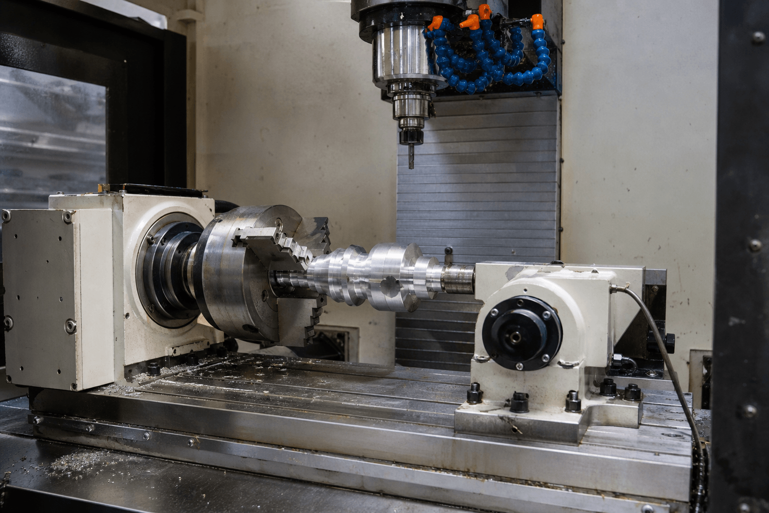
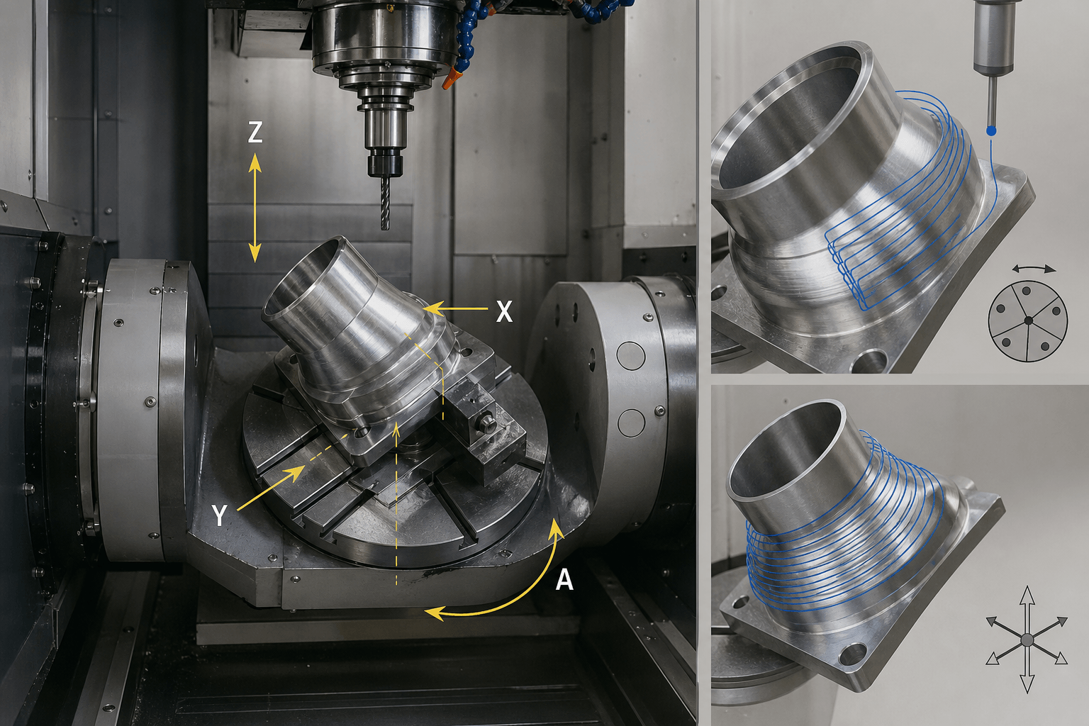
A 4 axis CNC machine controls three linear axes, X, Y, and Z, plus one rotary axis identified as A, B, or C according to the axis around which it rotates. The rotary axis may index a part between cuts or move continuously during cutting, so a machine that drills flats around a cylindrical housing is not necessarily capable of machining a continuous helical path.
For example, a cylindrical housing with radial flats may need only indexed 3+1 positioning, while a helical groove around the same housing requires coordinated rotary and linear motion during cutting. This distinction affects machine selection, programming, workholding, collision planning, and cost; the useful question is not simply whether a machine has a fourth axis, but what that axis can do within the available work envelope.
What the Fourth Axis Controls: Linear and Rotary Motion
In a conventional three-axis machining center, the tool and workpiece move relative to one another along X, Y, and Z. Adding one controlled rotary movement creates a four-axis configuration. A typically denotes rotation around X, B rotation around Y, and C rotation around Z, although the machine builder’s coordinate definition must always be checked.
Most add-on fourth-axis units rotate the workpiece rather than tilting the spindle. Horizontal machining centers may instead use an integrated rotary table, commonly with a vertical rotational axis. Trunnion and rotary-head designs also exist, so the axis letter alone does not define the physical arrangement.
Indexed 3+1 Versus Simultaneous Four-Axis Cutting
Indexed 3+1 machining
- The machine cuts using X, Y, and Z.
- The tool retracts to a safe position.
- The rotary axis indexes the workpiece to a commanded angle.
- The rotary axis clamps or holds position while the next feature is cut.
This mode suits holes, pockets, slots, or flats located on several sides. It can preserve relationships between those features without manually removing and reclamping the part, provided the fixture and tool can reach them.
Simultaneous four-axis machining
The rotary axis moves while one or more linear axes are cutting. Coordinated motion can generate helical grooves, wrapped profiles, changing radial features, or contours around a cylindrical surface. Tool position, feed behavior, rotary speed, and surface engagement vary along the path.
This requires a controller that supports coordinated four-axis interpolation, suitable CAM functionality, a correct machine model, and a validated postprocessor. A fitted rotary table does not by itself prove that simultaneous cutting is available.
For both modes, the posted program must match the machine’s axis direction, rotary limits, center of rotation, work offset strategy, and shortest-path behavior. Simulation should include the chuck, jaws, fixture, tailstock, spindle, toolholder, and machine travel limits rather than showing only the nominal part.
Operational Differences Between 3, 4, and 5 Axes
| Machine type | Access and motion | Setup implications | Planning demands |
|---|---|---|---|
| 3 axis | Three linear movements; the tool normally approaches from one fixed direction. | Different faces may require manual repositioning or dedicated fixtures. | Generally the simplest programming and collision model, but extra setups must be located and verified. |
| 4 axis | Adds one rotational degree of freedom. Operation may be indexed or simultaneous. | Can expose multiple faces around one rotational centerline. Features outside that access pattern may still need another setup. | Requires rotary datum control, additional clearance checks, suitable CAM and controller functions, and configuration-specific workholding. |
| 5 axis | Adds two rotational degrees of freedom through a table, trunnion, head, or combined arrangement. | Can orient complex surfaces and angled features from more directions, subject to travel and interference. | Introduces more kinematic, postprocessing, verification, calibration, and collision considerations. |
None of these machine classes is inherently better. A three-axis process may be the most direct choice for a simple plate. Four-axis machining can fit parts whose important features are arranged around one centerline. Five-axis equipment becomes relevant when the required tool vectors cannot be reached with one rotary degree of freedom. Geometry, tolerances, tooling, workholding, quantity, and available process knowledge determine the practical choice.
Parts That Fit a Four-Axis Process
| Part or feature | Potential four-axis fit | Limitation to review |
|---|---|---|
| Radial hole pattern on a housing | Index the body to drill or mill holes at defined angular positions. | Check drill length, chuck clearance, hole depth, and whether all angles share the same centerline. |
| Flats, pockets, or keyways around a body | Use indexed positions while retaining the original clamping datum. | Jaws or a tailstock may obstruct end features; some faces may remain inaccessible. |
| Helical groove or wrapped profile | Use simultaneous rotation coordinated with linear feed. | The controller, CAM system, postprocessor, rotary speed, and cutting strategy must support the path. |
| Contour around a cylindrical component | Continuous rotation can keep the surface presented to a fixed-orientation tool. | Tool angle remains constrained; undercuts and steep end features may require another configuration. |
| Long, slender shaft | Radial features may be indexed around the shaft. | Deflection, vibration, tailstock support, tool reach, and unsupported length can govern feasibility. |
| Multi-direction undercuts | Limited where the cutter requires several independent approach angles. | Five-axis machining, special tooling, turning with live tools, or another setup may be more suitable. |
A hypothetical automotive component might combine radial holes, wrench flats, and an end bore. A fourth axis could keep selected radial features aligned, while the end bore might still require a repositioning operation depending on spindle access. Readers evaluating related components can review the broader context of custom metal manufacturing for automotive and transportation equipment.
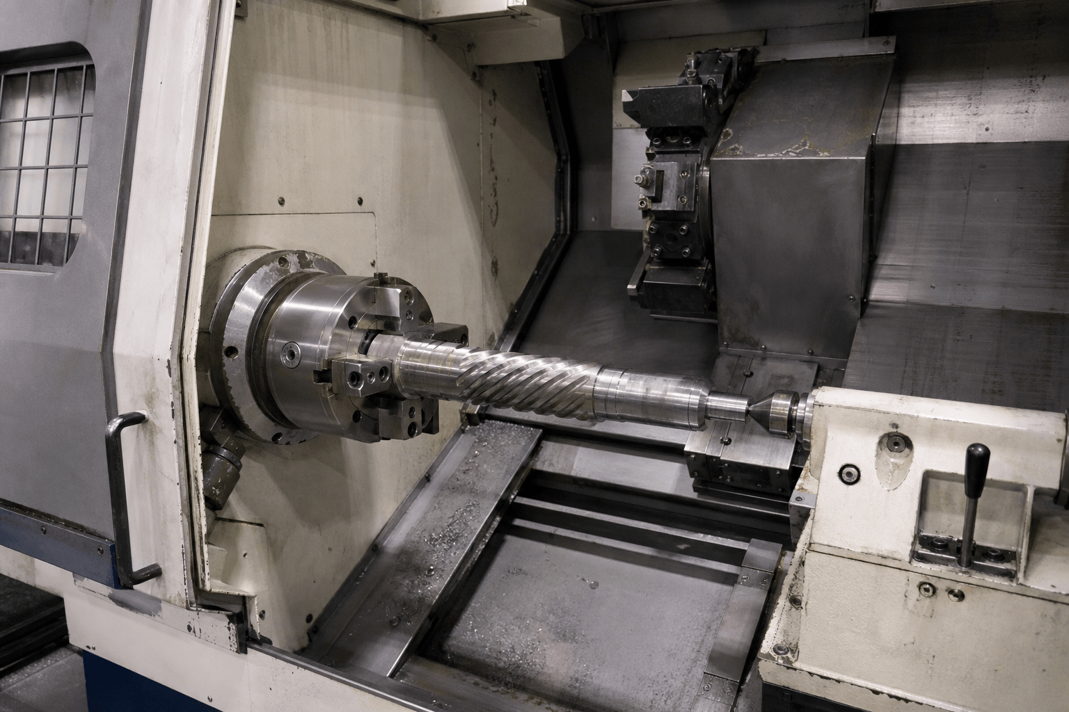
CNC turning remains a separate machining process. A turned blank may proceed to four-axis milling for cross-holes or flats, but this machining sequence does not make turning a form of four-axis milling.
Specifications That Define Usable Capacity
Nominal part diameter or table size is only a starting point. The complete rotating and cutting envelope determines whether the setup is physically and dynamically workable.
| Specification | What it controls | What to verify |
|---|---|---|
| Axis orientation and center height | Where the rotational centerline sits relative to the spindle and table. | Fixture height, tool approach, available Z travel, and clearance below the part. |
| Chuck or table dimensions | Possible gripping footprint and jaw arrangement. | Actual swept diameter, jaw projection, fastener access, and clamping length. |
| Allowable load and moment | Whether the rotary unit can support the fixture and workpiece. | Total mass, overhung center of gravity, cutting loads, and whether published limits apply horizontally or vertically. |
| Torque and holding capability | Resistance to cutting forces and ability to accelerate the load. | Continuous versus peak ratings, brake or clamp behavior, fixture inertia, and intended cutting mode. |
| Rotational speed | Whether the axis can follow the required indexed moves or continuous path. | Speed under the actual load, acceleration limits, duty cycle, and feed calculation method. |
| Linear travel and part length | Whether the tool can reach every programmed feature. | Chuck, part, tailstock, toolholder, tool-change, and retract envelopes at all angles. |
| Accuracy, repeatability, and backlash control | Angular positioning behavior and return to commanded locations. | Definitions, test conditions, load conditions, compensation method, and their relationship to feature tolerances. |
| Controller and feedback system | Available interpolation, synchronization, work offsets, and compensation. | Number of simultaneously controlled axes, rotary data handling, encoder arrangement, CAM compatibility, and postprocessor support. |
Vertical machines fitted with a table-mounted rotary unit can lose usable Y or Z space because the part sits above the table. Horizontal configurations may provide favorable chip flow or multi-face access for some parts, but pallet, tombstone, spindle, and fixture clearances still require evaluation.
Can This Part Use a 4 Axis CNC Machine?
Use the following application-fit worksheet before choosing a machine class or requesting a process review.
- Part envelope: Record maximum diameter, overall length, mass, and the fixture’s expected swept diameter.
- Feature directions: Mark every required tool approach. Determine whether they are distributed around one centerline or require a second independent tilt direction.
- Motion mode: Separate features that need angular indexing from paths that require rotation during cutting.
- Support: Identify jaw contact, datum surfaces, clamping distortion risks, and any need for a tailstock, steady support, or custom fixture.
- Critical relationships: Highlight positions, runout relationships, or profiles that should remain aligned within one setup.
- Clearance: Include tool length, holder diameter, spindle body, jaws, fasteners, supports, and safe retract moves.
- Production context: Record quantity, repeat frequency, expected setup time, inspection requirements, and acceptable changeover effort.
Implementation also brings programming, training, maintenance, and safety demands. Operators need procedures for rotary zero setting, work offsets, clamping, safe recovery, and program proving. Maintenance planning may include lubrication, cable and hose movement, seals, brake or clamp condition, backlash monitoring, and periodic verification according to the equipment supplier’s instructions.
Economic evaluation should use job-specific inputs: equipment or retrofit cost, integration, CAM and postprocessor work, fixturing, training, maintenance, setup hours, cycle time, inspection effort, and expected annual volume. A useful comparison is annual process difference = volume × per-part time or cost difference + annual setup difference. Compare that result with total implementation cost and production risk; do not assume that fewer setups automatically offset greater programming and equipment complexity.
Frequently Asked Questions
Is a 4 axis CNC machine the same as 3+1 machining?
Not always. The term 3+1 normally describes indexed operation: the rotary axis positions the part, then remains stationary while three linear axes cut. Some four-axis machines also coordinate rotary and linear motion during cutting. Controller functions, machine design, CAM software, and the postprocessor determine which mode is available.
What is the practical difference between 3 axis and 4 axis CNC machining?
A three-axis machine approaches the work from a fixed tool direction unless the part is manually repositioned. A fourth axis can present different sides around one rotational centerline and may support continuous rotary toolpaths. The practical result depends on fixture access, travel, clearance, programming, and feature geometry.
When is a 5 axis machine more appropriate than a 4 axis machine?
Five-axis machining may be more appropriate when required tool vectors need two independent rotational movements, such as compound-angle features, complex undercuts, or surfaces that cannot be reached around one rotary centerline. It also adds kinematic and collision complexity, so part geometry and process requirements should justify it.
What determines the cost of a 4 axis CNC machine or retrofit?
Cost depends on machine size and construction, rotary capacity, controller integration, feedback and clamping systems, simultaneous-axis capability, installation, CAM and postprocessor needs, fixturing, training, maintenance, and local support. A retrofit must also be checked for controller compatibility, available machine travel, electrical and mechanical integration, and the required safety functions.