
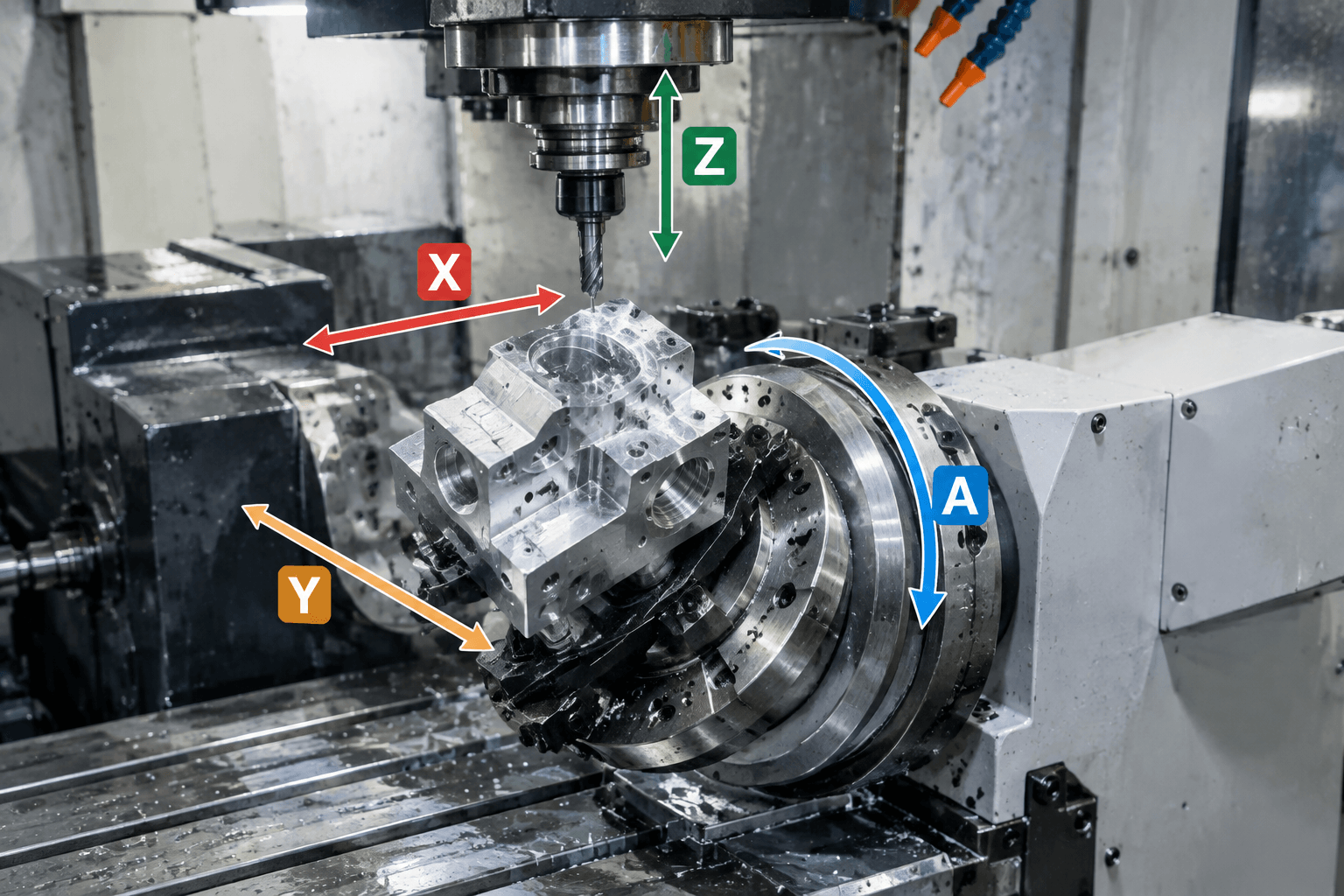
4 axis CNC machining uses three linear axes—X, Y, and Z—plus one rotary axis to expose additional faces or coordinate cutting around a part. The fourth axis does not universally tilt and rotate the workpiece; its orientation and motion depend on the machine configuration.
The practical question is whether that rotary movement gives the cutter useful access to your component. Indexed machining can position different faces before cutting, while simultaneous machining coordinates rotary and linear motion during the cut.
What Does the Fourth Axis Actually Do?
On a conventional 3-axis mill, the cutting tool moves relative to the workpiece along X, Y, and Z. A 4-axis arrangement adds rotation about one axis. Rotary axes are commonly identified as A, B, or C according to whether they rotate around X, Y, or Z, but machine builders may arrange the hardware differently. Depending on the machine configuration, the rotary unit may hold the workpiece around a horizontal centerline or rotate it on a vertical table.
Yes, a distinct 4-axis CNC machine exists, although the term can also describe a 3-axis machining center equipped with an integrated or added rotary unit. The important distinction is functional: the control, hardware, workholding, and programming system must support the required rotary operation.
Rotary-axis milling should not be confused with CNC turning. In turning, rotating stock is generally cut by a tool to generate rotationally symmetric geometry. In 4-axis milling, rotation primarily changes workpiece orientation or becomes one coordinated component of a milling toolpath. Some components may require both processes, but they remain conceptually distinct.
Indexed 3+1 or Simultaneous 4-Axis Cutting?
Two parts described as “4-axis machined” may have followed substantially different production sequences. Buyers should establish whether a drawing needs indexed positioning, continuous coordinated motion, or a combination of both.
| Operating mode | How it moves | Suitable feature examples | Important limitation |
|---|---|---|---|
| Indexed 3+1 machining | The rotary axis moves to a programmed angle and locks. Cutting then occurs using the linear axes. | Holes, slots, pockets, flats, or datum-related features distributed across several accessible faces | The machine does not rotate the part during the cutting pass. Indexing alone cannot produce every continuous curved surface. |
| Simultaneous 4-axis machining | The rotary axis moves while one or more linear axes move, creating a coordinated toolpath. | Helical details, changing profiles around a circumference, wrapped engraving, and some continuous rotary surfaces | Availability depends on the machine, control, CAM system, and supplier capability. A fitted rotary table does not automatically provide simultaneous cutting. |
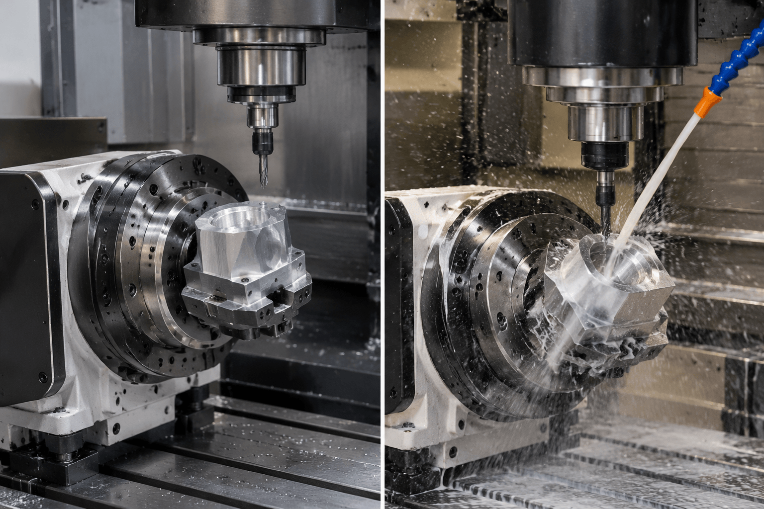
Indexed: rotate → stop and clamp → cut → rotate to the next angle.
Simultaneous: rotate and move linearly during the cutting pass.
Indexed machining can reduce manual handling when several faces are reachable from one rotary setup. This may help preserve relationships between features because they are produced without removing and relocating the workpiece between every face. It does not eliminate setup error, however; rotary-center calibration, fixture location, clamping behavior, tool condition, and programming remain relevant.
Does This Part Actually Benefit From 4-Axis Machining?
The strongest candidates have geometry distributed around a consistent rotary centerline or features on multiple faces that can be presented to the spindle by indexing. A visually complicated part is not automatically a good candidate.
| Part condition | Likely process fit | Reason to review |
|---|---|---|
| Holes or pockets on several sides | Often suitable for indexed 4-axis machining | One rotary setup may expose several faces while supporting angular or positional relationships. |
| Repeated features at defined angular positions | Strong indexing candidate | Programmed rotation can position each feature around a common axis. |
| Continuous profile around a shaft-like body | Potential simultaneous 4-axis candidate | Coordinated rotation may create geometry that would be inefficient or segmented in separate indexed positions. |
| Text, channels, or patterns wrapped around a cylinder | Potential wrapped-toolpath application | CAM can translate planar path movement into rotary motion, subject to geometry and control support. |
| Deep cavity behind adjacent walls | Requires access study; 4-axis may not solve it | Rotating the part cannot overcome every holder collision or unfavorable tool angle. |
| Undercuts requiring a second tool orientation | May need a special cutter, another setup, or 5-axis access | One rotary degree of freedom cannot present all undercut surfaces to the spindle. |
| Simple features on one face | Usually a straightforward 3-axis candidate | The rotary setup may add programming and fixturing effort without creating useful access. |
For example, consider a hypothetical rectangular housing with ports on four sides and a critical angular relationship between two holes. Indexed 4-axis machining may allow those faces to be addressed without repeatedly removing the housing. By contrast, a sculpted component with surfaces facing many unrelated directions may require broader 5-axis tool orientation. Neither approach is inherently superior; process fit depends on which movements the geometry demands.
Access Is Limited by More Than the Axis Diagram
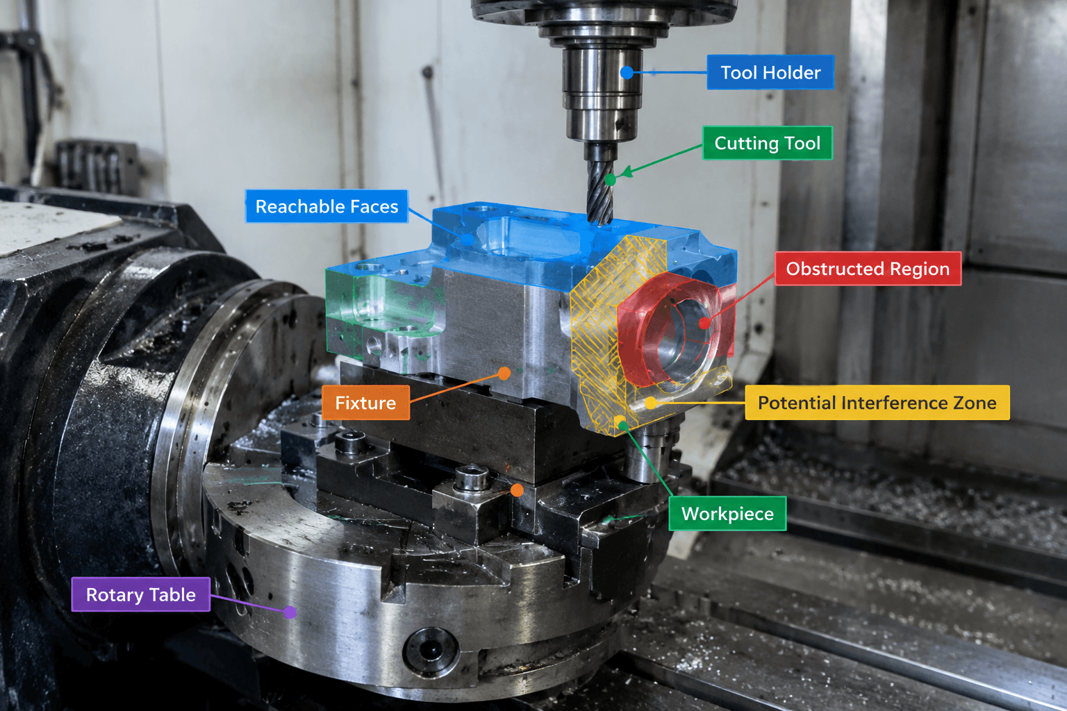
A CAD view may show that a face can rotate toward the spindle, yet the real setup can still prevent the tool from reaching it. The complete assembly—part, fixture, chuck or table, tool, holder, spindle, and surrounding machine structure—must remain clear throughout every commanded movement.
Reachable face: the cutting edge can approach at the required angle with adequate clearance.
Obstructed region: jaws, clamps, a tailstock, or the rotary body blocks the path.
Interference zone: the cutting edge may reach, but the wider tool holder or spindle body may collide.
Hidden geometry: a reverse-facing undercut remains inaccessible with the available axis orientation.
Long tools can reach past a fixture or into a deep feature, but added reach can reduce rigidity and change cutting behavior. Feature depth, wall height, neighboring geometry, cutter diameter, holder shape, and chip evacuation therefore influence whether a theoretically visible surface is practical to machine.
Workholding presents another constraint. The fixture must resist cutting forces while leaving the required faces open. A long or unevenly loaded component may also create balance, support, or clearance concerns as it rotates. Tailstock support or additional clamping may stabilize the part but can obstruct another region. Some components still need a second setup to machine the clamped end or a face outside the rotary envelope.
How to Evaluate a Drawing for Process Fit
No axis count can establish tolerance or surface-finish capability by itself. Results depend on the combined machine condition, rotary accuracy, setup, fixture stiffness, tooling, material response, feature geometry, cutting strategy, environmental control, and inspection plan. Feasibility should therefore be evaluated feature by feature.
- Identify the datum structure. Show how critical features are located and which surfaces establish the part coordinate system.
- Mark related features. Call out holes, pockets, faces, or profiles that must maintain positional, angular, or rotational relationships.
- Define the geometry completely. Supply a drawing and, where useful, a 3D model so the supplier can examine depths, radii, undercuts, wall conditions, and collision risks.
- State material and finish requirements. Material behavior, stock condition, coating allowances, texture requirements, and protected surfaces can affect process planning.
- Separate critical requirements from general ones. This helps determine where a controlled rotary setup or targeted inspection is necessary.
- Provide quantity and inspection expectations. These inputs influence fixture strategy, cycle planning, sampling, and whether dedicated inspection tooling is reasonable.
Features distributed around a component may require inspection from a common datum or measurement of angular positions about a defined centerline. The drawing should make those relationships explicit. The machining supplier can then propose how the part will be located, which features can remain in one setup, where a secondary operation is necessary, and how critical characteristics will be verified.
For a drawing-based review, send the part drawing or 3D model, material, quantity, critical tolerances, surface requirements, and the features that must maintain positional or angular relationships. Yishang’s custom CNC machining services for drawing-based components can provide process-fit feedback on rotary-axis access, setup strategy, workholding constraints, and whether 3-axis, indexed 4-axis, or simultaneous 4-axis machining is the appropriate route.
Frequently Asked Questions
Is a 4-axis CNC machine a distinct machine type or a 3-axis platform with a rotary axis?
It can be either. Some machines are designed with an integrated rotary axis, while other 3-axis machining centers use an added rotary unit. What matters for a project is the available axis orientation, work envelope, control functions, rigidity, and compatibility with the required toolpath.
Can all 4-axis CNC machines perform simultaneous cutting?
No. Some systems provide only indexed positioning, often called 3+1 machining. Simultaneous operation requires compatible machine hardware, CNC control functions, CAM programming, and proven production capability. Confirm the operating mode rather than relying only on the “4-axis” label.
When is 4-axis machining preferable to 5-axis machining?
Four-axis machining can be appropriate when the needed features are accessible through rotation around one centerline, such as multi-face holes or circumferential details. Five-axis machining may be more suitable when the tool must approach surfaces from multiple changing angles. The simpler viable setup—not the higher axis count—is generally the useful comparison.
What factors influence the cost of a custom 4-axis machined part?
Cost depends on material, stock preparation, geometry, feature access, programming, fixture complexity, tooling, number of setups, machining time, quantity, finishing, and inspection requirements. A rotary axis may reduce handling for one part but add unnecessary setup effort for another, so cost should be assessed from the drawing and production requirements.