
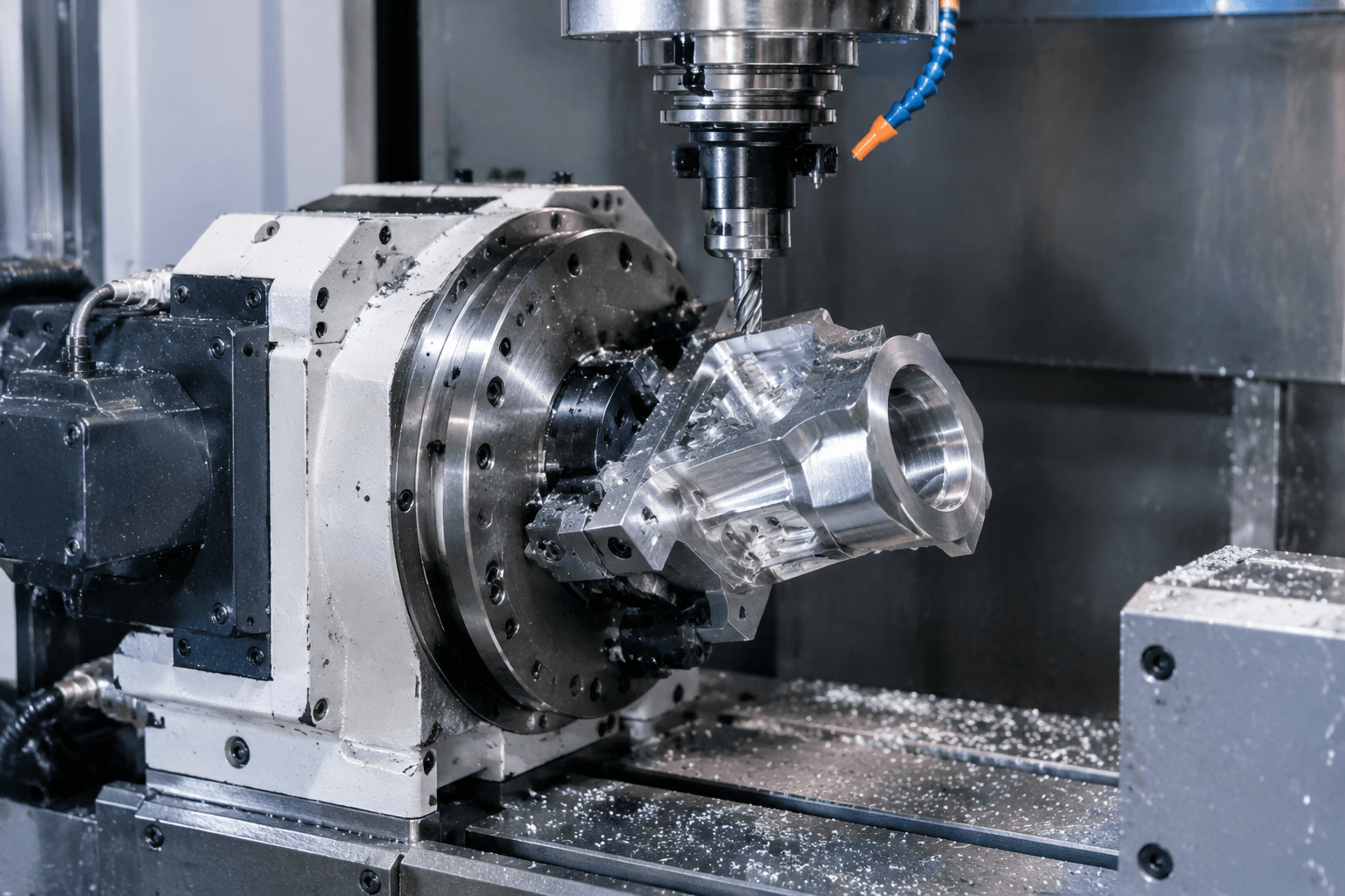
4 axis CNC machining combines the three linear movements of a standard milling setup with one rotary movement. For example, a metal workpiece can rotate around one axis so the cutter reaches a side face or follows features arranged around the part.
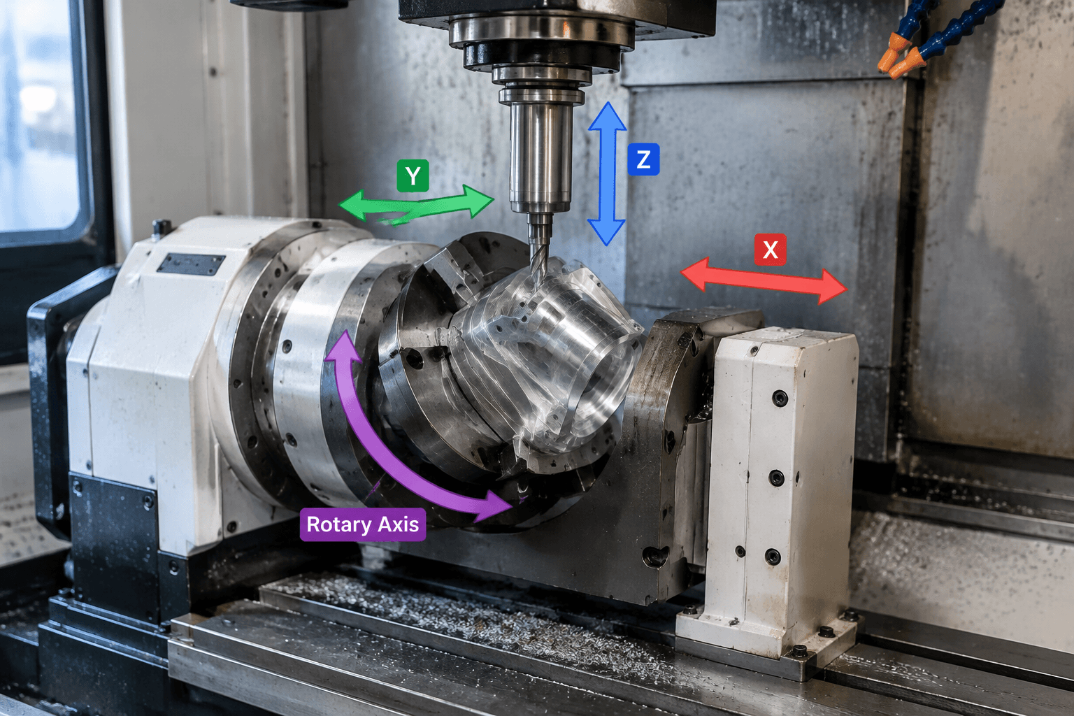
4 axis CNC means the machine controls X, Y, and Z linear motion plus one rotary axis, often identified as A, B, or C depending on the machine configuration. The rotary axis may reposition the workpiece between cutting operations, or it may rotate while cutting; these are different operating methods, and not every 4-axis machine supports simultaneous four-axis cutting.
For OEM engineers and procurement teams, the practical question is not whether four axes are automatically better. The useful question is whether the part has features that need access around a side, circumference, or angled surface, and whether that access can be achieved with the available workholding and machine configuration.
                 Z+
                 ↑
                 │       cutter
                 │         ↓
        Y+  ←────┼────→  Y-
              [ metal part ]  ↺ rotary axis
                 └──────────── X+
What Does the Fourth Axis Do?
In a 3-axis CNC milling process, the cutting tool or workpiece is positioned through X, Y, and Z. These movements let the tool approach the top and, depending on the setup, selected side areas of a part. A fourth axis adds controlled rotation. Instead of removing the workpiece and manually turning it, the rotary unit can present another face to the cutter according to the programmed sequence.
The rotary axis does not necessarily give the spindle a fourth linear direction. It changes the angular position of the workpiece, or in some configurations changes the orientation of the cutting system. On a milling center, the fourth axis is commonly implemented with a rotary table, rotary fixture, or similar workholding device. Whether the axis rotates the part horizontally, vertically, or around another direction depends on the equipment and setup.
This distinction matters when reading a drawing or discussing manufacturability. A part may have four controlled axes available, but the accessible area is still limited by the rotary unit, fixture, tool length, spindle clearance, and the geometry of the workpiece. A fourth axis also does not automatically improve accuracy, lower cost, or eliminate the need for careful datum planning.
4-axis CNC milling should also be kept separate from CNC turning. Turning uses a different machine configuration in which the workpiece normally rotates against a cutting tool. A turned component may later interface with a sheet metal assembly or machined bracket, but turning is not synonymous with four-axis milling. The same axis terminology can also appear in woodworking, although this article focuses on metal parts and industrial machining decisions.
Indexed and Simultaneous Four-Axis Machining
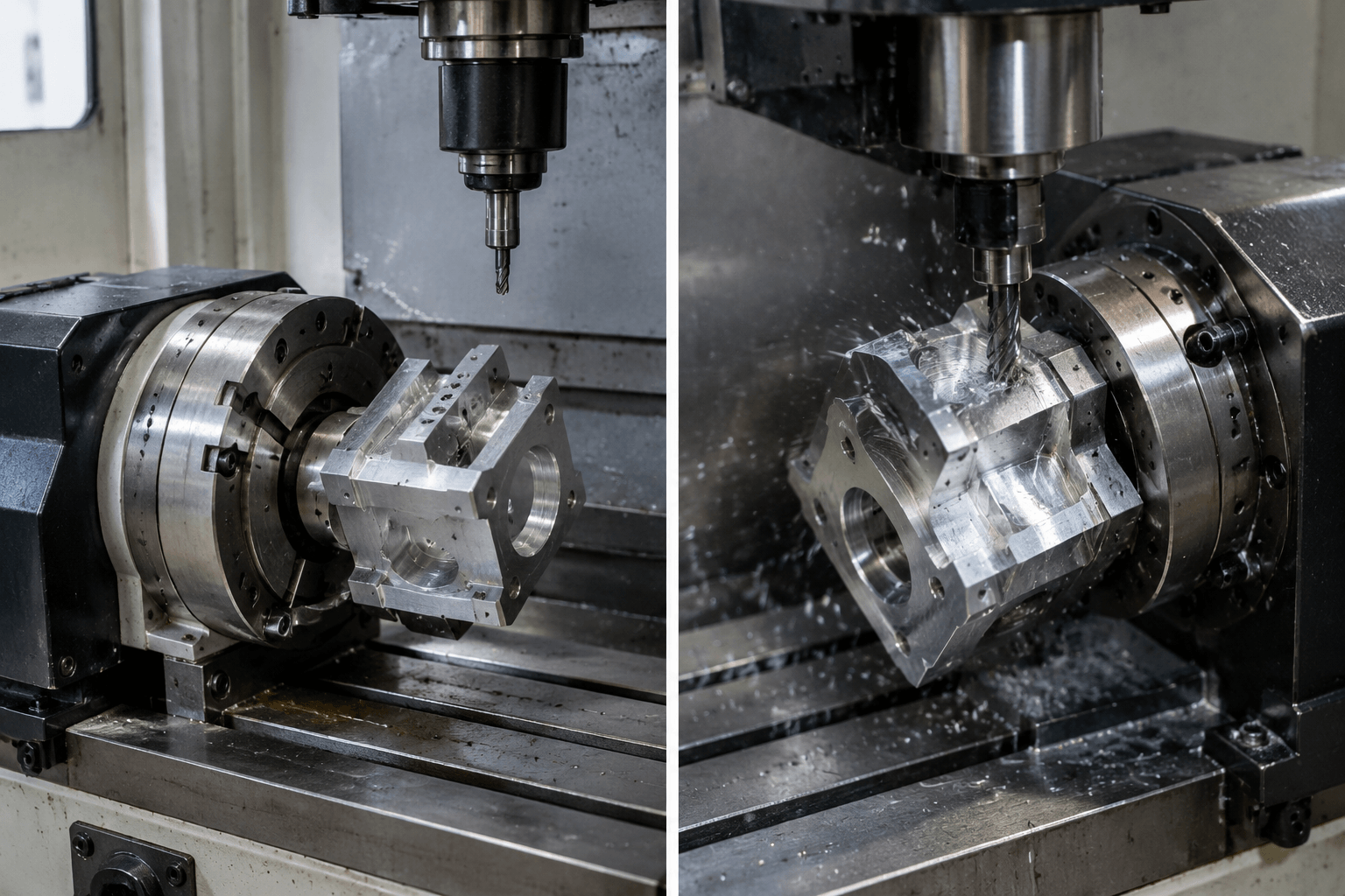
There are two important ways a rotary fourth axis can be used. The first is indexed machining. The rotary axis moves the part to a programmed angle, stops, and holds that position while the machine performs a conventional cutting operation. After one face or feature is complete, the part rotates to another angle for the next operation.
Indexed positioning can reduce repeated manual reclamping when features are distributed around a part. It may also help keep related features referenced to one setup, subject to the machine, fixture, datum strategy, and inspection requirements. However, the cutter is not continuously coordinating with rotary movement during the cutting pass. The part is positioned first, then machined.
The second method is simultaneous four-axis machining. Here, X, Y, Z, and the rotary axis move in coordinated motion while material is being removed. This can be useful for a toolpath that follows a changing position around a cylindrical or curved surface, such as a wrapped groove, repeated contour, or other feature whose location changes with rotation.
Indexed: cut at 0° → rotate to 90° → cut → rotate to 180° → cut.
Simultaneous: X/Y/Z movement and rotary movement progress together along one programmed toolpath.
Not all machines described as 4-axis machines can perform simultaneous four-axis cutting. The control system, rotary unit, post-processor, software, tooling, and machine kinematics all affect what can be programmed and executed. For an early design discussion, it is more accurate to describe the required feature and access direction than to assume that the phrase “4-axis” defines one universal capability.
Which Part Features Benefit from Rotary Access?
A fourth axis becomes relevant when the machining problem is mainly about access around the workpiece. A simple top-face pocket may be fully practical on a 3-axis machine. By contrast, a part with bolt holes on several radial faces may benefit from rotating the workpiece to present each face to the spindle.
Typical feature groups that may benefit include:
- Features on multiple sides: holes, slots, pockets, or milled flats arranged around a central body can sometimes be machined by indexing the part.
- Features around a cylindrical surface: wrapped grooves, repeated radial details, and contours that follow the circumference may use rotary movement during cutting, provided the equipment and programming support it.
- Angular or side access: a rotary setup may expose a side feature without creating a separate manual setup, although tool clearance and fixture interference still need review.
- Repeated features at known angles: indexed rotation can help organize a sequence of equivalent features around a part.
Rotary access is not a substitute for design review. The part still needs a stable datum scheme and workholding that will not obstruct the cutter. Deep cavities, enclosed features, undercuts, and compound surfaces may require a different machine orientation, specialized tooling, or additional axes. On a sheet metal assembly, machined interfaces such as mounting faces, tapped holes, or locating features must also be considered separately from the forming and fabrication operations used to make the sheet metal components.
Match the Feature to the Access Needed
The following comparison is a starting point for process selection. It does not replace a review of the part model, material, thickness, tool access, surface requirements, production volume, and inspection plan.
| Part requirement | Potentially suitable method | What to check |
|---|---|---|
| Top-face pockets, profiles, and drilled features | 3-axis CNC machining may be sufficient | Tool reach, side-wall access, workholding, and whether another setup is needed |
| Features on several known faces | 3-axis with multiple setups or indexed 4-axis machining | Datum transfer, fixture clearance, angular locations, and inspection access |
| Features distributed around a cylindrical surface | Indexed or simultaneous 4-axis machining, depending on the toolpath | Rotary-axis direction, control and programming support, cutter contact, and surface requirements |
| Deep side features, undercuts, or several changing tool angles | 5-axis machining may be more appropriate | Required tool orientation, collision avoidance, fixture design, and whether the geometry truly needs two rotary axes |
| Primarily rotational exterior or internal diameters | CNC turning may be the relevant process | Part proportions, rotational symmetry, cross-features, and any later milling operations |
The difference between 3-axis, 4-axis, and 5-axis machining is therefore geometric rather than a simple ranking. Three-axis machining can be efficient for accessible prismatic features. Four-axis machining adds rotary positioning or coordinated rotary movement around one axis. Five-axis machining adds another rotary degree of freedom, which can help maintain a changing tool angle or reach more complex surfaces. More axes do not automatically mean better results; they introduce different programming, fixturing, and inspection considerations.
For a broader view of how material, geometry, machining operations, and production requirements are evaluated together, see custom CNC machining for metal parts. Yishang manufactures custom sheet metal parts and metal products, supports OEM and ODM projects, and has more than 26 years of manufacturing experience with exports to more than 50 countries. The relevant process for a particular component should be confirmed from its drawings, 3D model, material, and functional requirements.
Frequently Asked Questions
Is 4-axis CNC always simultaneous?
No. A 4-axis machine may use the rotary axis for indexed positioning, where the part turns between cutting operations. Simultaneous four-axis machining coordinates rotary and linear movement during the cut, but that depends on the machine, control, software, post-processor, and setup.
How is 4-axis different from 5-axis CNC?
Four-axis CNC combines X, Y, and Z motion with one rotary axis. Five-axis CNC adds a second rotary degree of freedom, which can allow more changing tool orientations and access to complex surfaces. The correct choice depends on the actual features, clearances, and required tool angles.
What affects the price of a 4-axis CNC machine versus the cost of a machined part?
The purchase price of a machine is a capital-equipment question. The cost of a custom machined part is a production question affected by material, geometry, programming, setup, tooling, cycle time, finishing, inspection, quantity, and other requirements. These should not be treated as the same type of price.
When reviewing a metal part, start by marking every feature that requires access from a side, around a circumference, or at a changing angle. That feature map usually gives a more reliable basis for choosing among 3-axis, indexed 4-axis, simultaneous 4-axis, 5-axis, turning, or a combination of processes.