
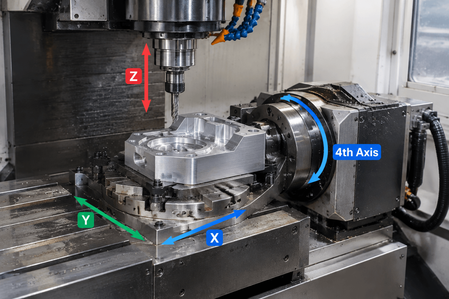
A 4 axis CNC mill adds one rotary axis to the three linear axes, but the rotary motion may be used in two different ways: to reposition and lock the workpiece, or to move continuously with the linear axes while cutting. Those operations are not interchangeable, even though both may be described as four-axis machining.
Quick answer: A 4 axis CNC mill controls movement along X, Y, and Z plus rotation around one axis, commonly called A, B, or C. Whether it can perform simultaneous four-axis cutting depends on its machine configuration and control, so define the required motion rather than relying on the machine label.
This distinction helps engineers and buyers match a part’s geometry to the motion it needs. A row of holes around a shaft may call for indexed positioning; a continuous helical surface may require rotary interpolation during the cut.
What the fourth axis changes
The X, Y, and Z axes describe linear movement in three perpendicular directions. The fourth axis is rotary: it turns the workpiece, the tool, or an axis assembly around one of those directions. On many milling setups, a rotary fixture holds and turns the workpiece while the cutting tool moves along the linear axes.
                 Z (linear travel)
                 ↑
                 │       Tool
                 │        ↓
       Y  ↗      │    ┌─────────┐
                 └────┤ Workpiece├──── X (linear travel)
                      └────┬────┘
                           ↻ A (example rotary axis)
Rotary-axis letters indicate the direction of rotation relative to the machine’s coordinate system: A is about X, B about Y, and C about Z. The letter does not, by itself, tell you where the rotary unit is mounted or how the part is oriented. For example, a rotary fixture may turn a part about an axis parallel to the machine’s X direction, making that rotation an A axis.
Adding a rotary axis changes tool access because the workpiece can be presented at different angular positions without being removed and manually reoriented for each face. That can support machining around a part’s circumference or reaching several sides, subject to tool clearance, fixture design, and the machine’s actual configuration.
Hardware and motion capability are separate questions. A machine may have a rotary axis that indexes between cutting operations without supporting coordinated rotary and linear movement during a cut. The term “four-axis” alone does not confirm simultaneous four-axis interpolation.
Indexed 3+1 and simultaneous cutting are different motions
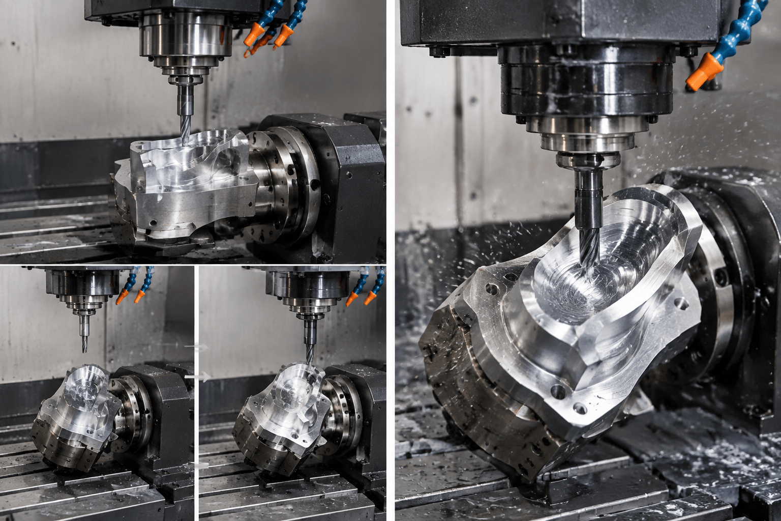
In indexed 3+1 machining, the rotary axis positions the workpiece at a selected angle and stops. The machine then cuts using its three linear axes. When the next face or angular position is needed, the rotary axis moves again and locks before cutting resumes.
In simultaneous four-axis milling, the rotary axis moves while the tool is cutting, coordinated with one or more linear axes. The tool path can therefore follow a surface that changes continuously around the rotary axis. The practical question is not whether the machine has four controlled axes; it is whether the rotary and linear axes need to move together during the cut.
INDEXED 3+1                         SIMULTANEOUS 4-AXIS
1. Rotate to angle                    Rotary axis moves during cutting
       ↻ stop                                   ↻
2. Lock rotary axis                   Tool path continues as the part turns
3. Cut with X, Y, Z                    X/Y/Z + rotary motion coordinated
       ───── tool path                              ~~~~~ tool path
Some parts commonly called “four-axis projects” need only indexed access. Others need continuous rotary contouring. Confirm which operation is intended instead of assuming the label implies one or the other. If a supplier’s terminology is unclear, ask whether the rotary axis is stationary during cutting or interpolated with the linear axes for the specified feature.
Match the motion to the geometry
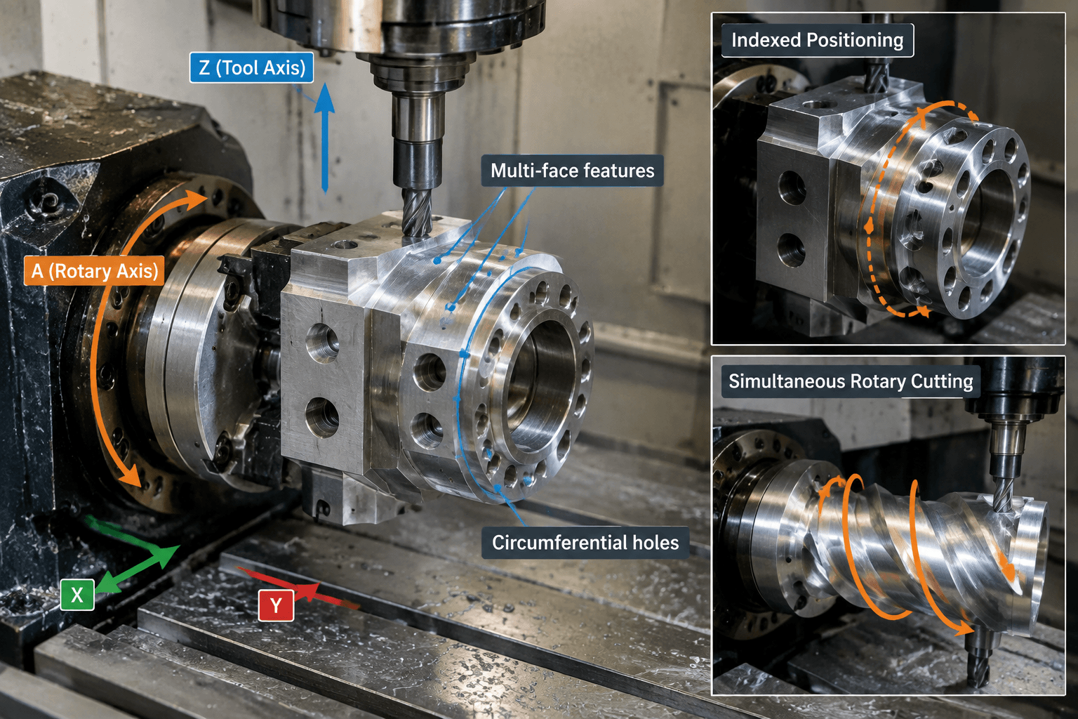
Indexed positioning suits features that can be machined from distinct, fixed orientations. Examples include holes on several sides of a block, flats spaced around a cylindrical part, or pockets and slots located at separate angular positions. A rotary fixture can present each region to the tool, after which the cut proceeds with the rotary axis stopped.
A circumferential pattern is not automatically a simultaneous-motion requirement. If each hole or slot is discrete and can be approached at a fixed angle, indexing may be sufficient. The design and tool approach still matter: a deep feature, obstructed surface, or angled tool requirement could change the setup needed.
Simultaneous rotary interpolation may be needed when a feature’s position changes continuously around the part. A helical groove is a familiar example: as the tool advances along the part, its angular position must also change. Wrapped contours and some continuous surfaces around a cylindrical component may have the same requirement.
INDEXED FEATURES                      CONTINUOUS CONTOUR
   ○       ○                             / / / / /
  ┌───────────┐                         / / / / /
  │  ○     ○  │   Rotate, stop, cut    ┌───────────┐
  └───────────┘   at each position      │   ↻       │
 Multiple faces or holes                 Helix or wrapped path
These examples describe motion, not guaranteed manufacturing feasibility. The tool must reach the surface without colliding with the workpiece or fixture, and the setup must hold the part securely through the required orientations. Rotary clearance and workholding can constrain what is practical. A supplier may also propose a different setup or process if it produces the required geometry more directly.
Compare axis configurations by commanded motion
More axes do not automatically mean better accuracy, surface finish, cycle time, or cost. The useful comparison is which motions each setup can command for the part, and whether those motions are needed to create its critical features.
| Configuration | Motion during cutting | Typical geometry fit |
|---|---|---|
| 3-axis | X, Y, and Z linear movement; workpiece orientation stays fixed during a setup. | Features reachable from one setup orientation, such as faces, pockets, and holes within available tool access. |
| Indexed 3+1 | Three linear axes cut at a time; one rotary axis repositions and locks between cuts. | Separate features on multiple faces or at distinct angular positions. |
| Simultaneous 4-axis | Three linear axes and one rotary axis can move in coordination during cutting. | Continuous contours that wrap or change position around the rotary axis. |
| 5-axis | Three linear axes plus two rotary degrees of freedom; the exact arrangement depends on machine design. | Geometry that needs a second changing tool or workpiece orientation beyond what one rotary axis provides. |
A three-axis setup may be enough when all required surfaces are accessible from its fixed orientation. Indexed 3+1 can add access to separated sides without requiring continuous rotation during the cut. Simultaneous four-axis motion is relevant when the feature itself calls for coordinated rotary movement. A second rotary degree of freedom in a five-axis setup may help orient the tool or workpiece in another direction, but it is unnecessary when the required geometry can be produced with fewer axes.
Machine categories and labels can also be used inconsistently. A profile machining center may offer rotary or angular access for profile work, but that does not make every such machine equivalent to a four-axis CNC mill. CNC turning removes material as a rotating workpiece is cut by a tool; it is not the same operation as four-axis milling. Mill-turn machines combine process capabilities, but the term still does not establish which milling interpolation is available.
Specify the required result in the model and drawing
Give the supplier enough information to understand both the geometry and its reference frame. The 3D model should represent the finished part, while the drawing should identify the datums used to locate and inspect critical features. If the rotary orientation matters, define the intended rotary axis relative to those datums rather than relying on an unlabeled view or an assumed machine setup.
An annotated drawing can identify the primary datum, the centerline or direction of the intended rotary axis, and the angular zero or reference position for features distributed around the part. Mark critical surfaces and features clearly. If a wrapped or helical surface must remain continuous, call out the relevant surface or feature and state that it requires continuous contouring; do not leave that requirement to be inferred from a rendered model alone.
- For indexed access: “Features on the four indicated faces may be machined in separate angular positions. Continuous rotary motion during cutting is not required.”
- For continuous contouring: “The marked helical surface requires continuous rotary interpolation coordinated with the linear tool path.”
- When process is flexible: “Meet the drawing requirements for geometry and datums; propose the machining approach that produces the specified result.”
These statements describe the outcome or motion requirement without assuming that a particular machine label guarantees it. They also help distinguish a mandatory process requirement from a preferred manufacturing method. If a process is contractually required, state that separately from the geometry and inspection requirements.
Before finalizing the manufacturing method, provide the 3D model and corresponding drawing, datum scheme, intended rotary-axis orientation, and identification of any surfaces requiring continuous contouring. Include the material and quantity context. Request a motion-based review through Custom CNC Machining From First Sample to Repeat Production to clarify whether the part calls for indexed access, simultaneous fourth-axis interpolation, or another machining approach.
Frequently Asked Questions
Is there such a thing as a true 4-axis CNC mill?
Yes. A mill can have three linear axes and one rotary axis that moves in coordination with them during cutting. However, not every machine described as four-axis supports simultaneous interpolation, so confirm the required control motion.
Can a 3+1 machine produce parts commonly described as 4-axis projects?
Often, if the features are separate and can be cut after rotating and locking the workpiece at each required position. If a surface must be machined while the part rotates continuously, indexed 3+1 motion alone does not describe that operation.
When does a part require 5-axis milling instead of 4-axis milling?
A second rotary degree of freedom may be needed when one rotary axis cannot provide the changing tool or workpiece orientation required by the geometry. The answer depends on feature access and machine configuration, not simply on part complexity.
Does adding a fourth axis automatically improve accuracy or surface finish?
No. Axis count alone does not establish accuracy or finish. Results depend on the machine, setup, tooling, programming, workholding, material, and specified geometry. An added rotary axis changes available motion and access; it is not a universal quality improvement.