
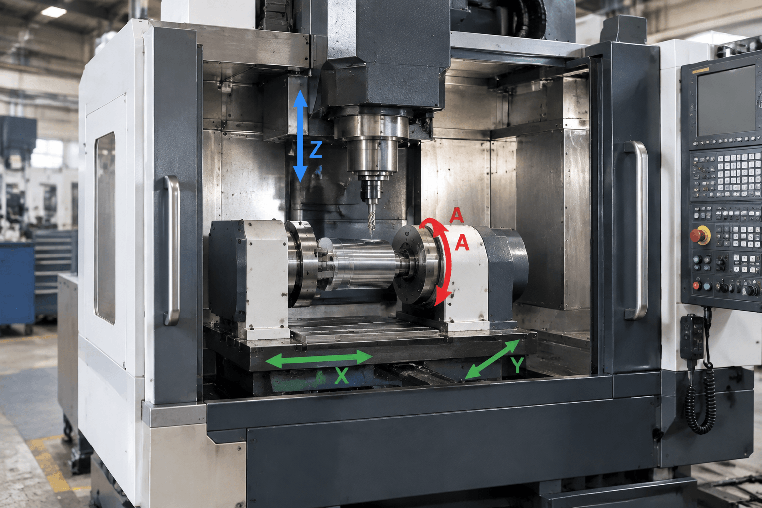
A 4 axis CNC milling machine is a milling system that combines X, Y, and Z linear movement with a controlled rotary axis. The fourth axis rotates the workpiece or fixture so the cutting tool can reach features on multiple faces or around a circumference with less manual repositioning.
For example, after milling a flat surface, the machine can rotate the part 90 degrees and machine an adjacent face while the workpiece remains in the same fixture. Depending on the machine, controller, and CAM system, this rotation may be indexed between cutting operations or coordinated with linear motion during cutting.
How the Four-Axis Motion Model Works
The first three axes describe linear movement. Although the physical machine arrangement varies, they are normally interpreted as follows:
- X axis: left-to-right movement.
- Y axis: front-to-back movement.
- Z axis: vertical movement toward or away from the workpiece.
- Fourth axis: rotation around one of the linear axes.
                 Z
                 ↑
                 │      Cutting tool
                 │          ↓
Y  ↗        ┌────┴─────────────┐
           │    Workpiece      │  ↻ A-axis rotation
           └───────────────────┘
                 → X
A rotary axis aligned with X is commonly called the A axis. Rotation around Y may be called B, while rotation around Z may be called C. Machine builders and controllers can use different configurations, so buyers should confirm the actual orientation rather than relying only on the axis letter.
The distinction between indexed and simultaneous operation is also important. In indexed, or 3+1, machining, the rotary unit moves the workpiece to an angle and locks it while conventional three-axis cutting takes place. In simultaneous four-axis machining, the rotary and linear axes can move together during a cutting path. A machine fitted with a rotary table is not automatically capable of simultaneous operation; the controller, drives, machine design, and CAM software must all support it.
Rotary-Axis Components and Workholding
A fourth axis is more than an extra direction in a CNC program. It introduces hardware, workholding, control, and clearance requirements that must function as one system.
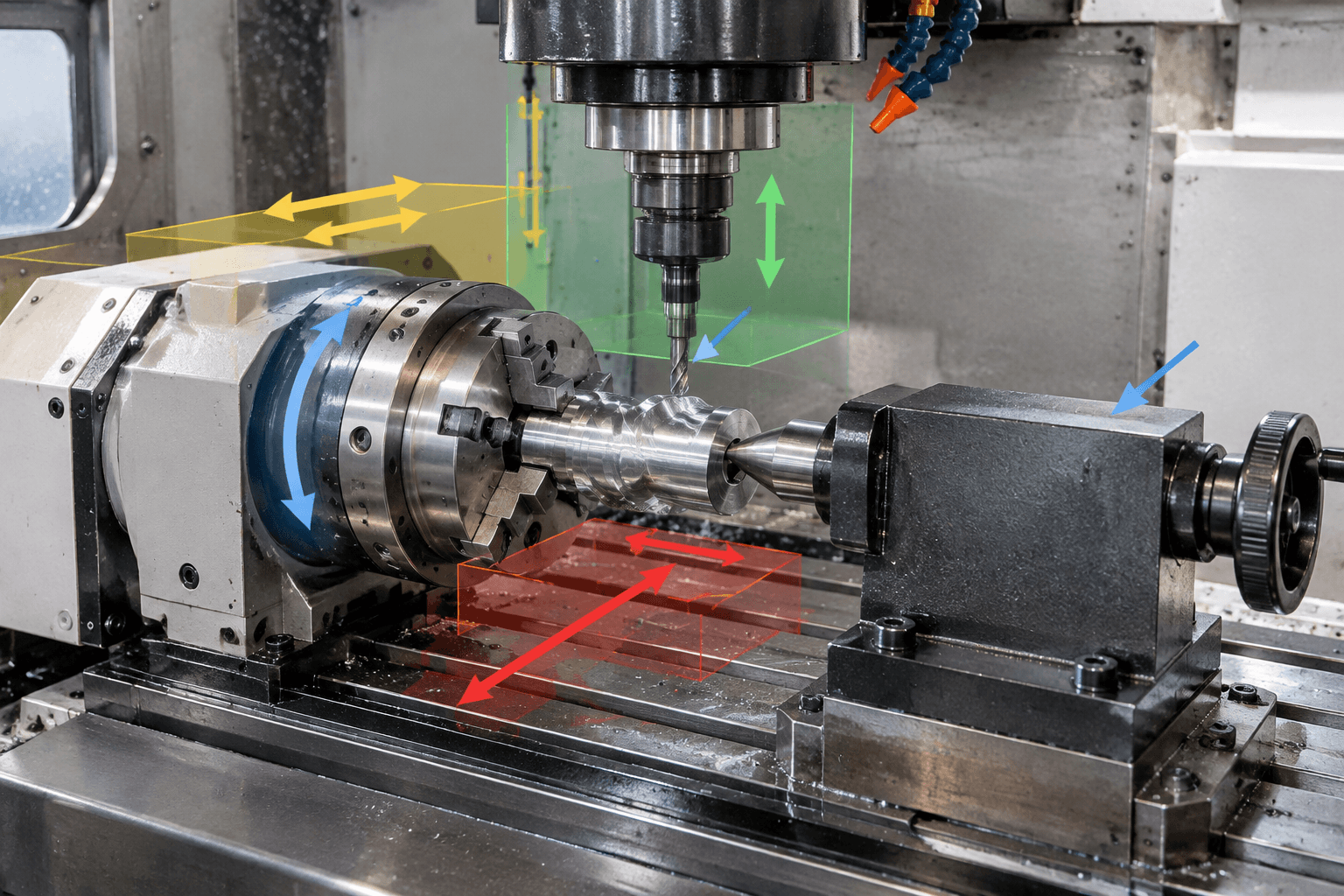
- Rotary table or indexer: This unit generates and controls angular movement. Relevant characteristics include its orientation, center height, load rating, clamping method, available rotation, and positioning performance.
- Chuck, collet, or custom fixture: The workholding method connects the part to the rotary unit. A chuck may suit cylindrical stock, while a collet can provide compact, concentric holding for suitable diameters. Irregular castings, blocks, and fabricated components may require a purpose-built fixture.
- Tailstock or secondary support: A long workpiece may need support opposite the rotary unit. The tailstock can reduce unsupported length, but it also occupies table space and may restrict tool access.
- Spindle and cutting tool: The spindle provides cutting speed and torque. Tool diameter, flute length, holder size, and gauge length affect whether the cutter can reach the feature without colliding with the chuck, fixture, or neighboring geometry.
- CNC controller and CAM system: The control must interpret rotary positions and coordinate the required moves. CAM software must generate suitable indexed or simultaneous toolpaths and account for rotary direction, limits, and safe retract movements.
- Probing and setting equipment: A probe may help establish work offsets, find rotational centerlines, or check features in the machine. Its availability does not eliminate the need for an appropriate datum strategy and independent inspection.
Clearance deserves particular attention. The nominal table travel may look sufficient on a specification sheet, yet the installed indexer, chuck, tailstock, tool holder, and guarding can substantially reduce usable space. The complete setup should therefore be considered as a three-dimensional assembly.
Reading 4-Axis Milling Specifications Against Part Requirements
A specification sheet describes the machine under stated conditions. It does not, by itself, confirm that a particular part will fit, that every feature is reachable, or that the drawing tolerances can be maintained. The following matrix connects common specification fields to practical part questions.
| Specification field | What it describes | What to verify for the part |
|---|---|---|
| Linear travels | Nominal X, Y, and Z movement | Whether the part, fixture, rotary unit, and required approach moves remain inside the usable travel |
| Table size and load | Mounting area and permitted load under defined conditions | Total mass and footprint of the rotary device, workholding, support, and workpiece |
| Rotary capacity | Permitted work size or load for the rotary assembly | Part diameter, offset center of gravity, cutting forces, fixture mass, and support arrangement |
| Center height | Distance from the mounting surface to the rotational centerline | Whether the swing diameter clears the machine table, enclosure, spindle, and tooling |
| Rotary travel and limits | Available angular movement | Whether continuous rotation is required or cables and limits restrict the programmed path |
| Spindle speed and torque | Available spindle performance across its operating range | Suitability for the material, cutter diameter, tool engagement, and required cutting conditions |
| Spindle taper and tool capacity | Compatible holders and available automatic tool positions | Whether all roughing, finishing, drilling, chamfering, and inspection tools can be accommodated efficiently |
| Rotary resolution and positioning data | How angular commands are measured and the stated positioning behavior | How angular error could affect feature location at the part radius; resolution must not be treated as guaranteed part accuracy |
| Controller functions | Supported interpolation, coordinate handling, compensation, and program features | Whether the intended indexed or simultaneous strategy is supported |
| Probing options | Workpiece or tool measurement functions available on the machine | Datum access, rotational alignment, tool setting, in-process checks, and probing clearance |
The usable work envelope should be evaluated after the complete fixture is modeled. A long part between a chuck and tailstock may fit by length but still collide when rotated. Likewise, a large-diameter component may fit above the table at one angle yet interfere with the spindle housing or tool holder during cutting.
Material cannot be assessed from spindle speed alone. Aluminum, stainless steel, carbon steel, engineering plastics, and other materials place different demands on spindle torque, machine rigidity, cutter geometry, coolant delivery, chip evacuation, and workholding. Part geometry and tool engagement also influence the appropriate cutting strategy.
Which Part Geometries Benefit from a Rotary Axis?
Four-axis milling is most useful when controlled rotation exposes features that would otherwise require repeated manual setups. Typical geometry-led applications include:
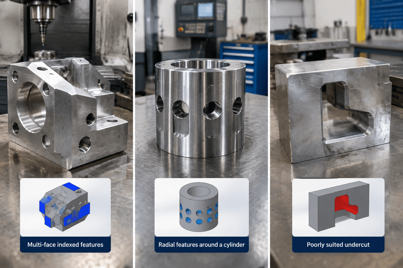
- Features on several faces: Holes, pockets, counterbores, threads, and datum surfaces distributed around a prismatic part can often be indexed into position.
- Radial features: Cross-holes, slots, flats, and keyways located around cylindrical or polygonal workpieces can be machined at controlled angular positions.
- Wrapped profiles: Some grooves, markings, and contoured paths can be programmed around a circumference when the control and CAM package support the required coordinated motion.
- Long components needing consistent orientation: Parts supported between a rotary unit and tailstock may benefit when multiple angular features share a common centerline.
Reducing manual repositioning may improve datum consistency and lower handling time, but one setup does not automatically mean that every surface is accessible. The chuck or fixture still covers part of the workpiece, and the tool generally cannot reach a back face blocked by the holding arrangement.
Deep internal undercuts, features hidden behind shoulders, and complex surfaces requiring changes in tool angle may need special cutters, another setup, or a different machine configuration such as five-axis machining. A cylindrical appearance also does not make a part a turning application by default. CNC turning rotates the workpiece as the primary cutting motion, whereas a four-axis mill uses a milling spindle and adds controlled workpiece orientation or rotation.
Why Machine Specifications Do Not Guarantee Part Results
Positioning accuracy, repeatability, and controller resolution describe different aspects of machine behavior. None should be copied directly into a drawing-tolerance promise. Finished-part results depend on the entire process, not just the axis count or a single specification value.
Workholding can deform thin walls or allow movement under cutting load. Long tools may deflect, while worn tools can change size and surface condition. Thermal changes affect the machine, spindle, fixture, and workpiece. Material condition, stock variation, toolpath strategy, cutting forces, burr formation, and the sequence in which features are machined can also influence the result.
Rotary error has a geometry-dependent effect. A given angular deviation produces a larger linear displacement farther from the rotational centerline. Consequently, feature radius, datum selection, chuck runout, fixture alignment, and rotary-axis calibration all matter when holes or surfaces must maintain an angular relationship.
Inspection planning is equally important. Buyers should identify critical dimensions, datum references, angular relationships, surface requirements, and any features that cannot be measured easily after removal from the fixture. Machine probing can support setup and process control, but final acceptance should follow the drawing and the agreed inspection method.
The practical decision therefore comes from reviewing the machine specification together with the part model, setup concept, tooling, material, production quantity, and inspection plan.
For a process-focused review, send Yishang your part drawing or 3D model, material, critical dimensions and tolerances, and expected quantity. Yishang supports B2B OEM and ODM custom manufacturing projects and can assess whether four-axis CNC machining is an appropriate approach without assuming that axis count alone guarantees feasibility. Learn more about custom CNC machining from first sample to repeat production.
Frequently Asked Questions
Is a rotary table automatically capable of simultaneous four-axis cutting?
No. Some rotary tables are intended mainly for indexed positioning, where rotation stops before cutting begins. Simultaneous machining requires compatible machine drives, CNC control functions, programming, and CAM output. Confirm the complete system rather than assuming capability from the presence of a rotary unit.
How is a 4-axis milling machine different from a 4-axis lathe?
A four-axis milling machine primarily cuts with a rotating milling tool while linear axes and a rotary workholding axis position the part. A lathe primarily rotates the workpiece against a cutting tool. A lathe may have additional axes and live tooling, but its process architecture remains distinct from four-axis milling.
Can a 4-axis mill machine all sides of a part in one setup?
Not always. Rotation can expose several side faces, but surfaces covered by the chuck or fixture remain inaccessible. End features may also be blocked by a tailstock. Tool reach, spindle clearance, and part geometry determine whether another setup is required.
Does a 4-axis machine produce tighter tolerances than a 3-axis machine?
Not automatically. A fourth axis may reduce repositioning and help maintain relationships between features, but achievable tolerances still depend on machine condition, rotary alignment, workholding, tooling, material, thermal behavior, process control, and inspection. The drawing must be reviewed feature by feature.