
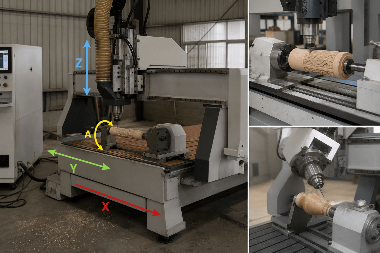
A 4 axis CNC wood router is a computer-controlled routing machine with three linear movements—X, Y, and Z—plus a fourth controlled movement that may rotate the workpiece or pivot the spindle. Yes, 4-axis CNC routers exist, but the label does not identify one universal machine architecture; that distinction determines whether the router suits angled panels, curved surfaces, wrapped parts, or multi-sided components.

What the Four Axes Actually Control
In a conventional 3-axis router, the tool or gantry travels along three linear coordinates. X commonly represents movement across the machine bed, Y represents travel along its length, and Z raises or lowers the spindle relative to the workpiece. This arrangement is effective for flat sheets, pockets, profiles, drilling patterns, and many three-dimensional surfaces that remain accessible from above.
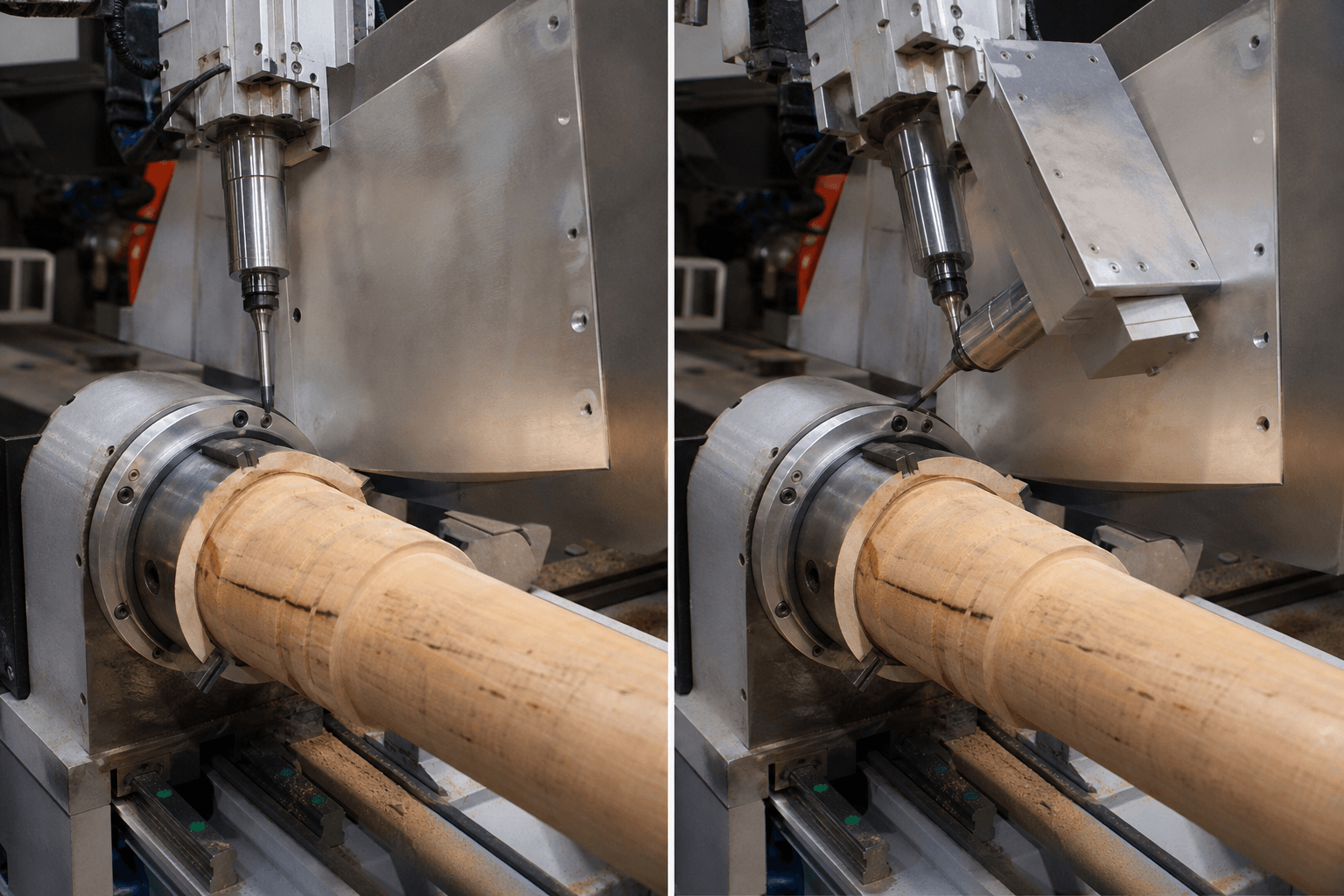
A fourth axis adds controlled angular movement. On a rotary-axis configuration, the workpiece turns around a defined centerline while the cutting tool continues to use linear motion. The axis may be called A, B, or C depending on the direction of rotation and the controller convention. On a swinging-spindle configuration, the spindle head pivots relative to the workpiece. The spindle’s angular travel, pivot point, tool length, and clearance envelope then affect which surfaces the cutter can reach.
These are not interchangeable descriptions. A rotating cylindrical blank and a pivoting spindle can both be promoted as “4-axis,” yet they address different geometry. The first continuously or incrementally exposes the circumference of a part. The second changes the tool’s approach angle to an inclined, curved, or multi-face surface. Some machines may also use a fourth axis for indexing only, while others coordinate it with X, Y, and Z during a cutting move.
Rotary Workpiece or Swinging Spindle? Compare the Architecture
The most important early evaluation question is simple: what physically moves when the fourth axis is commanded? Ask for a motion diagram or demonstration using the type of part you intend to produce.
| Configuration | What moves | Typical geometry fit | Questions to verify |
|---|---|---|---|
| Rotary-axis router | A chuck, rotary table, or other workholding unit rotates the workpiece around a controlled centerline. | Posts, columns, legs, cylindrical carvings, wrapped artwork, and parts requiring access around a central axis. | Rotary diameter, usable length, center height, chuck and tailstock arrangement, indexing or continuous rotation, and collision clearance. |
| Swinging-spindle router | The spindle pivots through an angular range while the workpiece is usually held on a table or fixture. | Angled joinery, inclined faces, selected multi-face parts, sculpted surfaces, and curved or oblique areas that need a different tool approach. | Angular range, pivot location, tool-length limits, spindle clearance, control method, and whether the motion is indexed or coordinated while cutting. |
| Indexed fourth axis | The rotary unit or spindle moves to a programmed angle, stops, and the machine cuts with the new orientation. | Parts with distinct faces or repeated operations at known angular positions. | Available index increments, clamping behavior, zero-point repeatability, and whether the controller supports the required post-processor. |
| Simultaneous 4-axis | The fourth axis changes position continuously or in coordinated motion with one or more linear axes during a toolpath. | Wrapped or continuously changing surfaces, variable-angle cuts, and geometry where tool orientation must follow the form. | True simultaneous interpolation, supported axis combinations, CAM post-processor, feed calculation, and collision simulation. |
A rotary attachment can sometimes be mounted on a flat-bed router, but that does not automatically make the machine equivalent to a swinging-spindle router. The workpiece may need to be removed from the vacuum area, the available envelope may shrink, and the usable diameter can be much smaller than the advertised table width. Conversely, a pivoting spindle does not automatically provide continuous access around a long cylindrical component.

Indexed and Simultaneous 4-Axis Routing Follow Different Workflows
The phrase “4-axis” says nothing by itself about whether the axes move together. A basic indexed workflow can be understood as a series of controlled reorientations:
- The operator establishes the work coordinate system and secures the part.
- The fourth axis moves to a programmed angle or rotational position.
- The machine stops the angular movement and cuts using the available linear axes.
- The axis indexes to another position, and the next toolpath is executed.
- The part is inspected for registration, seams, uncut areas, and interference between operations.
This can reduce manual repositioning for parts with several defined faces, but it is not the same as continuously following a wrapped or flowing surface.
In simultaneous 4-axis routing, the controller coordinates the fourth axis with the linear axes while the cutter is engaged. A simplified example might involve a rotary axis turning a post while X or Z advances the tool along its length. For a swinging spindle, the pivot angle may change as the cutter follows an inclined or sculpted surface. The CAM system must calculate the motion, and the post-processor must translate that calculation into commands the specific controller understands.
Not every CAD/CAM package, controller, or post-processor supports the same combinations. Confirm whether “4-axis” means indexing, simultaneous interpolation, or both. A simulation should also account for the spindle body, collet, tool holder, fixture, chuck, tailstock, and the actual part—not only the cutter tip.
Choose the Configuration Around the Part, Not the Label
4-axis routing becomes useful when a part’s geometry or process sequence makes a single top-down approach inefficient. A rotary configuration may suit a furniture post with features distributed around its circumference. A swinging spindle may be more appropriate for an angled furniture component or an inclined panel where the cutting tool needs a controlled approach angle. Sculptures, molds, models, signs, doors, and irregular furniture components can each require different combinations of axis travel and workholding.
| Part or operation | Potentially suitable architecture | Workholding and access considerations |
|---|---|---|
| Flat sheet with pockets and profiles | 3-axis may be sufficient; a fourth axis is not automatically necessary. | Vacuum table or T-slot fixture can hold the sheet, subject to material, size, and cutting forces. |
| Long post, column, or turned-style decorative part | Rotary axis with chuck and, where needed, tailstock. | Verify center height, usable diameter, unsupported length, end access, and clearance around the rotating blank. |
| Angled panel or multi-face furniture component | Swinging spindle or indexed rotary fixture, depending on the faces and approach angles. | A T-slot fixture may provide flexible location. Check whether clamps obstruct the tool at the intended angles. |
| Wrapped carving or continuously changing circumference | Simultaneous rotary-axis routing may be appropriate. | The CAM path must match the rotary centerline, and the control must support coordinated motion without collisions. |
| Irregular sculpture, mold, or model | Architecture depends on undercuts, surface slopes, and required tool orientation; a 4-axis machine may still have access limits. | Use a dedicated fixture or vacuum/T-slot combination. Verify tool reach and whether reclamping is unavoidable. |

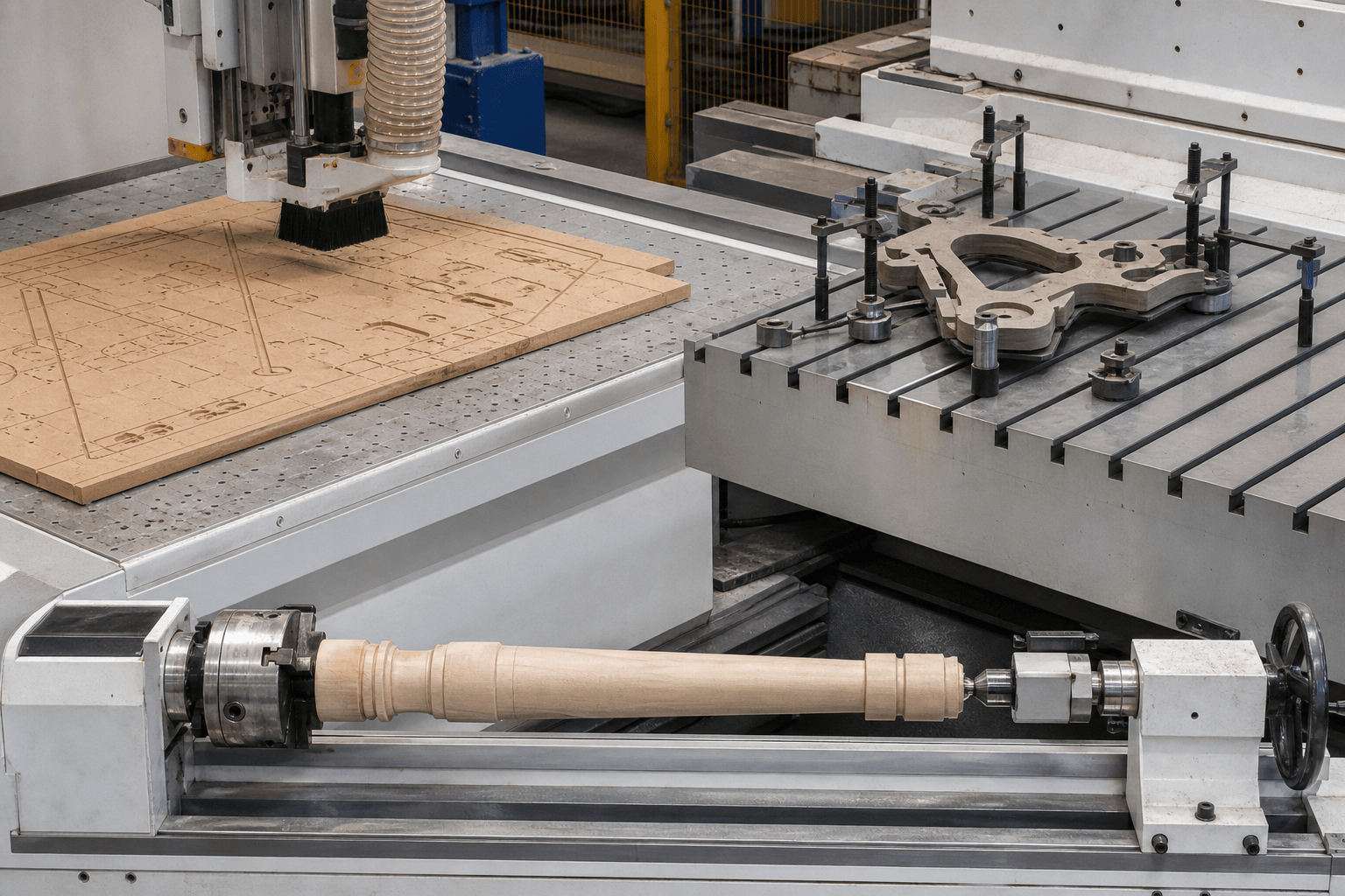
Vacuum tables are commonly considered for sheet work, while T-slots and custom fixtures can locate irregular components. A chuck-and-tailstock arrangement supports a different class of long rotary parts. In every case, the fixture must leave enough clearance for the spindle, tool holder, clamps, and moving axis. If the design requires machining the underside or a blocked face, determine whether the part can be indexed, whether it must be reclamped, and how the new datum will be established.
How to Read a 4-Axis Router Specification
Once the architecture is understood, compare specifications in groups rather than focusing on one headline number. The following fields normally require clarification:
- Linear working envelope: confirm usable X, Y, and Z travel after accounting for the table, fixture, spindle nose, and safety clearances.
- Rotary envelope: ask for usable rotary diameter, length, center height, and end-access limits. A flat-bed dimension does not define rotary capacity.
- Fourth-axis motion: identify the axis designation, angular or rotational range, pivot point, indexing resolution, continuous rotation capability, and mechanical stops.
- Spindle and tooling: verify interface, collet or holder options, tool-length limits, cooling requirements, automatic tool-change arrangement if included, and access around the tool.
- Controller and CAM: confirm supported file workflow, simultaneous interpolation, indexing functions, post-processor availability, coordinate transformation, simulation, and operator setup requirements.
- Table and workholding: establish whether the configuration includes a vacuum table, T-slots, rotary unit, chuck, tailstock, or only mounting provisions. Check how these options affect the working envelope.
- Feed rate, accuracy, and repeatability: request definitions, measurement conditions, material and geometry assumptions, and whether the values refer to positioning, cutting results, or a particular axis.
- Site requirements: confirm footprint, electrical supply, air requirements if applicable, dust extraction, installation conditions, maintenance access, and operator safety provisions.
Precision claims should never be evaluated without a test method. Wood species, stock dimensions, tool condition, temperature, fixturing, acceleration, and measurement equipment can all affect results. Similarly, a faster programmed feed rate does not automatically mean higher production output if tool changes, workholding, dust removal, finishing, or inspection dominate the cycle.
Frequently Asked Questions
Is a 4-axis CNC wood router the same as a CNC router with a rotary attachment?
Not necessarily. A rotary attachment turns the workpiece around a centerline, while another 4-axis design may pivot the spindle. A machine can also use a rotary attachment only for indexing rather than simultaneous cutting, so the mechanical arrangement and controller functions must be confirmed.
Can a 4-axis wood router cut all sides of a part in one setup?
It may reduce reclamping for some multi-face or wrapped parts, but “all sides” is not guaranteed. Chucks, clamps, fixtures, spindle bodies, tool holders, and the machine envelope can block areas. Undersides and deep recesses may still require a new setup or a different machine architecture.
What software and controller functions are needed for simultaneous 4-axis routing?
The CAD/CAM workflow must generate the intended fourth-axis motion, and the post-processor must match the controller’s axis convention and interpolation functions. Confirm simultaneous support, coordinate transformation, toolpath simulation, and collision checking rather than assuming that any 4-axis file will run on any machine.
Why do prices vary so widely among machines labeled as 4-axis routers?
The label may cover a simple indexed attachment, a full rotary setup, a swinging spindle, or a simultaneous system. Price is also affected by working envelope, spindle and tooling configuration, automatic tool changing, table design, controller, CAM package, installation, and support. Comparing the architecture and included scope is more useful than comparing the label alone.
The correct 4 axis CNC wood router is therefore defined by motion architecture, not by the number printed in a product title. First identify whether the fourth axis rotates the part or pivots the spindle; then establish whether it indexes or moves simultaneously, and finally check the usable envelope, workholding, software, tooling, and measurement conditions behind every specification. If the actual requirement is a custom metal component rather than routed wood, review custom CNC machining from first sample to repeat production and share the metal-part drawing through that separate process.