
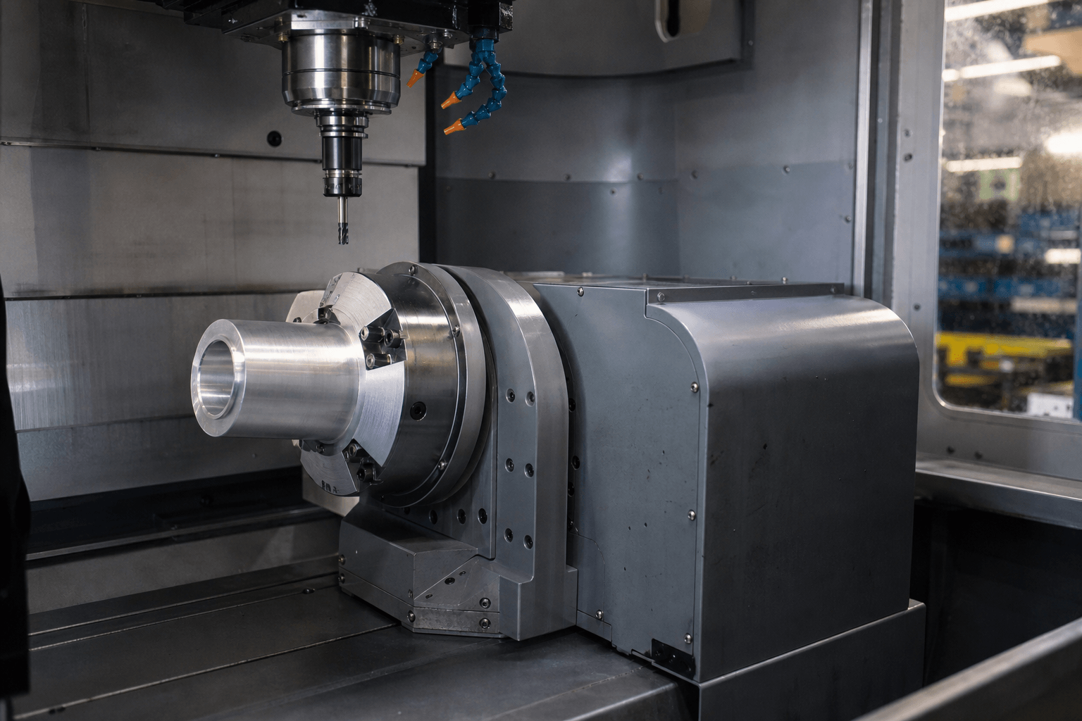
4 axis machining adds controlled rotation to the X, Y, and Z linear motions of a CNC machine. The rotary axis, commonly identified as A when it rotates around X, can position another face for cutting or move continuously while the tool cuts. This additional motion can reduce manual repositioning and make circumferential or multi-face features practical, but it does not automatically make a process faster or more accurate. The CAD geometry, rotary centerline, workholding, toolpath, post-processor, machine configuration, and inspection plan must all describe the same physical setup.
A model-to-part discrepancy often begins when one of those elements uses a different reference. A wrapped feature may be modeled from one cylinder diameter while the CAM operation uses another. A part may be programmed around its nominal centerline but held with an offset. A collision-free toolpath in a simplified simulation may become unsafe after the chuck, holder, fixture, or stock is represented accurately. Planning 4 axis machining therefore requires a connected workflow rather than a toolpath choice in isolation.
What the Fourth Axis Changes
In ordinary 3-axis machining, the cutter moves along X, Y, and Z while the workpiece remains in a fixed orientation. Features on another side generally require a new setup, a repositioned fixture, or another machine operation. In a four-axis setup, a rotary device turns the workpiece around a defined centerline, allowing the program to present different faces to the cutter or coordinate rotation with linear motion.
There are two main workflow choices:
- Indexed 4-axis machining: The rotary axis moves the part to a specified angle and remains stationary while the machine cuts with its linear axes. This approach suits holes, pockets, slots, flats, and other discrete features distributed across several faces.
- Simultaneous 4-axis machining: The rotary axis moves while one or more linear axes are cutting. This approach supports continuous paths around a cylindrical surface, helical features, changing contours, and geometry that cannot be divided cleanly into separate angular positions.
Indexed and simultaneous machining use the same additional axis in different ways. Indexing treats rotation as automated repositioning. Simultaneous cutting treats angular position as part of the toolpath itself. Some parts need both: indexed operations for discrete faces and simultaneous motion for a continuous circumferential feature.
Choose a Strategy from the Feature Geometry
The presence of a cylindrical blank does not by itself require rotary machining, and a prismatic part can still benefit from indexed access. The deciding questions are where the features lie, whether their relationships depend on a common rotational datum, and whether the tool must cut while the part turns.
| Feature condition | Likely approach | Planning focus |
|---|---|---|
| Features accessible from one direction | 3-axis machining | Stable workholding, tool access, and a clear planar datum |
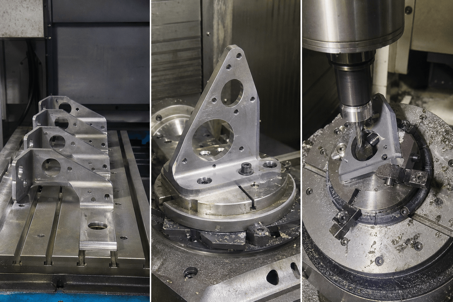
| Holes, pockets, flats, or slots on several defined faces | Indexed 4-axis machining | Angular orientation, feature-to-feature relationships, and clearance at each index |
| Repeated features distributed around a centerline | Indexed or simultaneous 4-axis machining, depending on feature shape | Rotary datum, angular spacing, and how each feature is generated |
| Text, grooves, or profiles wrapped around a cylinder | Simultaneous 4-axis machining may be appropriate | Wrap diameter, surface definition, seam behavior, and tool orientation |
| A continuous contour that changes as the part rotates | Simultaneous 4-axis machining | Coordinated motion, engagement, tool reach, and machine-aware simulation |
| Features blocked by the fixture or inaccessible at useful rotary angles | Revised setup, additional operation, or another machining approach | Physical access rather than axis count alone |
Multiple 3-axis setups can remain the more practical choice when the geometry is simple, the required faces are easy to locate independently, or rotary workholding would create poor support or limited access. Five-axis machining may be considered when the tool must also change its orientation relative to complex surfaces. The suitable process follows the feature geometry and setup constraints; it should not be selected solely by comparing the number of axes.
Prepare CAD Geometry for Rotary Toolpaths
A CAD model can be geometrically valid yet unsuitable for the intended rotary strategy. Rotary CAM depends on information that may not be obvious from the finished solid: the intended rotation axis, the controlling cylindrical surface, the angular start position, and whether a feature should follow the surface or merely appear similar in a fixed view.
Establish the centerline and controlling diameter
The modeled part, stock, fixture, and CAM setup should share a clearly defined rotary centerline. If the feature was created around a different axis or offset from the physical setup, angular motion can place it incorrectly even when its dimensions are correct in the model.
Wrapped paths also depend on the diameter or surface used for mapping. A path developed on one diameter does not represent the same surface distance when applied to another. This matters when the stock is oversized, the feature lies above or below a nominal cylinder, or the finished surface changes diameter along its length. The programmer should identify whether CAM is using a constant cylinder, the actual model surface, or another reference supported by the selected strategy.
Check continuity and the wrap boundary
Features crossing the angular start and end boundary require particular attention. A continuous-looking CAD feature may be divided into separate edges at that boundary, and a CAM system may interpret those edges as separate cuts or choose an unexpected direction. Small gaps, overlaps, projected curves, or discontinuous faces can also interrupt toolpath generation.
Emboss, sweep, and wrap functions are examples of ways CAD or CAM software may create circumferential geometry, but they are not universal requirements. For example, Autodesk products may expose operations named Emboss, Sweep Toolbody, Wrap Toolpath, or Wrap Cylinder. Their behavior and availability depend on the product and version. Regardless of the command name, the manufacturing review should confirm the resulting face geometry, reference diameter, depth definition, and continuity instead of relying on the visual appearance alone.
Model the manufacturing condition
Sharp internal corners, deep recessed details, and features close to workholding may be valid design elements but difficult to reach with a practical cutter and holder. The model should distinguish finished geometry from stock, fixture allowances, and any material intentionally left for later operations. Where a wrapped feature intersects a flat, hole, shoulder, or changing diameter, inspect the actual intersection rather than assuming a two-dimensional profile will transfer without distortion.
Plan Orientation, Workholding, and Datums Together
Setup planning begins by aligning the intended part axis with the machine’s physical rotary axis. The angular zero position must also correspond to a recognizable model and inspection reference. Without that relationship, a program can produce individually correct features at the wrong orientation relative to a keyway, flat, hole pattern, or mating face.
- Define the functional datum structure. Identify which surface or axis controls location along the part, which centerline controls rotation, and which feature establishes angular zero. Avoid choosing convenient programming references that cannot be reproduced during setup or inspection.
- Select workholding for the actual geometry. A chuck, collet, dedicated fixture, or another holding method may be appropriate depending on the part shape, available gripping region, and access requirements. The fixture must resist cutting forces without covering required features or forcing excessive tool extension.
- Evaluate support. Long or slender workpieces can deflect or vibrate. Additional support may help, but it becomes another object that must be included in access and collision checks. Support placement also needs to account for finished surfaces and tool travel.
- Confirm the machining sequence. Roughing can change the stiffness of the remaining material. Removing too much support early may make later circumferential finishing less stable. A sequence may therefore retain material, divide operations, or change support conditions before final features are cut.
- Represent the setup in CAM. Stock, jaws, fixture bodies, supports, and relevant machine components should be located from the same references used on the machine.
Rotary orientation also affects chip evacuation and tool access. A feature that is reachable at one angle may collect chips or place the holder close to the fixture at another. Reviewing the complete rotation is more reliable than validating only the start and end positions.
Select Tools and Cutting Strategies for Rotary Geometry
Tool selection should account for cutter diameter, flute length, overall reach, holder clearance, material, and the local shape of the part. A longer tool may reach past a chuck or shoulder, but the added projection can reduce rigidity. A smaller cutter may enter narrow geometry, but it changes engagement and chip evacuation. These tradeoffs should be resolved against the actual feature and setup rather than through a universal rotary-tool rule.
For indexed work, conventional pocketing, drilling, contouring, and surface strategies can often be applied after each angular position is established. The programmer should still check whether every indexed orientation preserves clearance and whether retract motion is safe as the part moves between positions.
For simultaneous work, tool engagement can change continuously as the surface rotates under the cutter. The strategy should control how the path approaches the part, crosses any wrap boundary, maintains depth relative to the intended surface, and exits the cut. Direction changes deserve review because they can alter cutting conditions or leave visible transitions on continuous surfaces.
Cylindrical and multi-face parts also require a deliberate chip-control plan. Cavities can rotate into positions where chips remain trapped, and a fixture can block their escape. The appropriate response depends on material, cutter, coolant or air strategy, feature orientation, and machine environment. These are process-planning considerations, not separate manufacturing processes.
Validate the Program Before Cutting
Verification should progress from geometric intent to executable machine motion. A toolpath preview alone is not enough because it may show the cutter relative to the model without representing the behavior of the post-processor, machine limits, rotary direction, holder, or fixture.
- Review the CAD and CAM references. Confirm the part axis, angular zero, stock, controlling diameter, feature depth, and setup origin.
- Inspect the generated toolpath. Look for discontinuities, unexpected reversals, movement across the wrap boundary, excessive linking motion, and changes in contact or engagement.
- Use the correct post-processor configuration. The post must match the intended machine and rotary arrangement. Axis naming alone does not establish compatibility; rotary direction, positioning conventions, limits, and controller behavior must agree with the physical configuration.
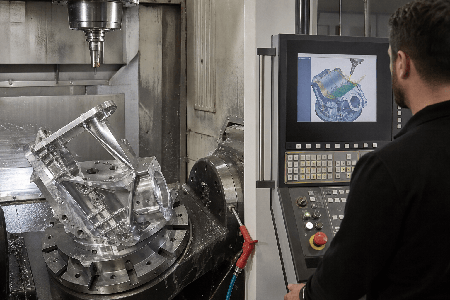
- Run machine-aware simulation. Include the tool, holder, stock, fixture, chuck or collet, supports, and relevant machine components. Check cutting moves, indexing moves, retracts, tool changes, and the full range of rotary motion.
- Review the posted output under the shop’s established controls. Confirm work offsets, tool data, rotary commands, and safe positioning before production execution.
- Plan inspection from the same datum logic. Verify not only individual feature sizes but also angular location, axial position, concentric relationships, and feature-to-feature orientation around the rotary centerline where those relationships matter to function.
Inspection access can differ from machining access. Features distributed around a cylinder may require repositioning, a suitable fixture, or a measurement method capable of relating them to the rotary datum. Defining that plan before machining helps reveal ambiguous drawing requirements and references that are difficult to reproduce.
For a technical feasibility review, provide the 3D model or drawing, critical feature relationships, material, quantity, and the areas requiring circumferential or multi-face machining. Yishang’s custom CNC machining support can review whether the geometry points toward 3-axis, indexed 4-axis, or simultaneous rotary machining and identify manufacturing information that should be clarified before production.
Where RFQ Assumptions Create Cost and Production Risk
Many sheet metal fabrication problems begin before production starts. If drawings, tolerances, finish expectations, material grades, or assembly requirements are unclear, suppliers may quote based on different assumptions. That can make prices difficult to compare and may lead to rework, cosmetic rejection, assembly misalignment, or production delays later.
For OEM buyers, the goal is not simply to request the lowest price. The goal is to make sure each supplier is quoting the same manufacturing reality. Before confirming an order, clarify which dimensions are fit-critical, which surfaces are cosmetic, whether prototypes must match batch-production conditions, and how finished parts will be inspected.
Frequently Asked Questions
What 4 axis machining details should buyers define before requesting a quote?
Buyers should define the functional requirement, drawing notes, critical dimensions, material or process expectations, and any inspection points related to 4 axis machining. This helps suppliers quote the same manufacturing scope instead of making different assumptions.
How can RFQ details affect cost, fit, or lead time?
RFQ details can change tooling, forming, welding, finishing, inspection, or rework requirements. If buyers do not clarify it early, two supplier quotes may look comparable while covering different production risks.
Why should drawing requirements be reviewed before prototype approval?
drawing requirements may look acceptable on a single sample but become harder to control during batch production. Buyers should confirm whether the prototype reflects the same process, finish, and inspection conditions expected for production.
What inspection points matter most for 4 axis machining projects?
Important inspection points usually include fit-critical dimensions, holes or mating areas, cosmetic surfaces, finish build-up, welded or formed features, and any dimensions that affect downstream assembly. These points should appear in the RFQ or drawing notes.
How can buyers reduce prototype approval risk before batch production?
Buyers can reduce risk by clarifying drawings, locking key material and finish assumptions, defining inspection timing, approving a representative sample, and confirming which dimensions or surfaces require tighter process control.
How can Yishang help review 4 axis machining requirements?
Yishang can review drawings, RFQ notes, material requirements, tolerance expectations, finish details, samples, and assembly needs to identify unclear assumptions before quoting or batch production.