
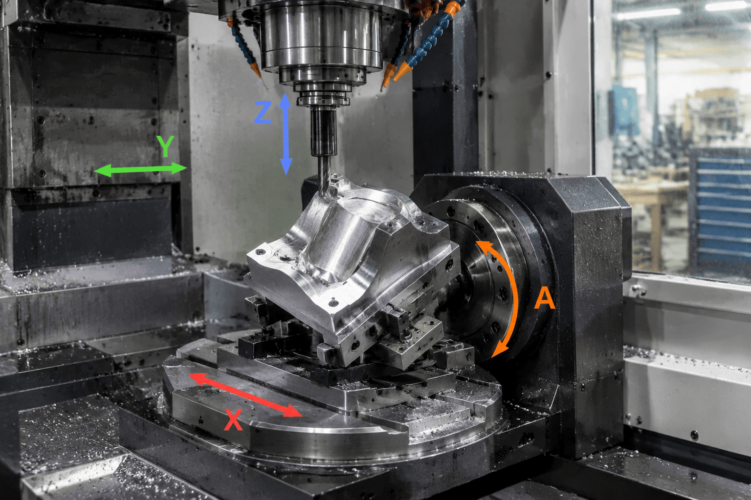
A 4 axis mill is a CNC milling machine with three linear axes, X, Y, and Z, plus a rotary axis that turns the workpiece relative to the cutting tool. That rotation can bring another face of a part into reach without removing and repositioning the part by hand.
For example, a fixture can hold a rectangular component while the rotary axis presents several sides for drilling or milling. Whether the machine can cut as the part rotates, rather than only after it stops at an indexed angle, depends on its control and configuration.
What the Fourth Axis Adds
On a typical vertical machining center, X and Y provide horizontal positioning and Z moves the tool vertically. A fourth axis adds rotation, commonly through a rotary table that holds the workpiece or its fixture. It changes which features the spindle can reach; it does not replace any of the three linear axes.
In indexed 4-axis milling, the table turns to a programmed angle and holds position while the machine cuts. This is useful for features on several faces or at repeated angular positions. In simultaneous 4-axis milling, the rotary axis moves during cutting, allowing a toolpath to follow certain features around a part. A machine described as a 4 axis mill should not be assumed to support both modes. The rotary hardware, control, programming capability, and intended setup need to be confirmed.
Part Geometries That Benefit From Rotary Access
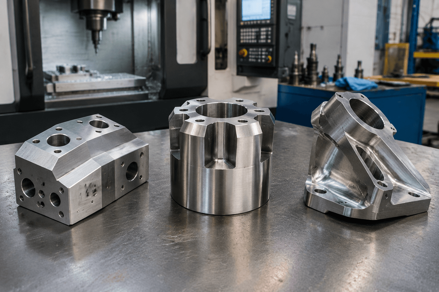
A prismatic housing with holes or pockets on multiple sides is a straightforward indexed-milling candidate. Rotating the held part can expose each reachable face to the spindle. That may reduce manual repositioning, but a face covered by the fixture, or a feature that the cutter cannot approach, can still require another setup.
A cylindrical body with a repeated pattern of radial holes or flats is another possible fit. Indexing can place each feature at its required angle. A feature that follows a path around the body may call for coordinated rotary cutting, provided the machine and control support it and the tool can reach the full path.
Rotary access is not the same as unrestricted angular access. A deep undercut, an angled feature hidden behind a shoulder, or a surface requiring the tool to tilt relative to the workpiece may remain inaccessible on a conventional 4-axis setup. Part orientation, cutter length, fixture shape, and the direction of approach matter as much as the number of programmed axes.
How to Read the Machine Specifications
The supplied Leadwell V-30iF configuration lists a 20 HP spindle, 10,000 RPM maximum spindle speed, a 24-tool automatic tool changer, and a full fourth-axis rotary table. These figures describe this stated configuration, not every 4 axis mill. They are useful starting points, but none independently establishes that a particular part can be machined.
| Stated feature | What it helps evaluate | What still needs confirmation |
|---|---|---|
| 20 HP spindle | Available spindle power is relevant to cutter selection and the planned depth and type of cut. | Suitable cutting parameters depend on the material, cutter diameter, tool engagement, and spindle performance at the required speed. |
| 10,000 RPM maximum speed | The speed range helps assess whether a proposed tool and operation can run at an appropriate cutting speed. | A maximum RPM alone does not establish performance across all materials, tools, or operations. |
| 24-tool automatic tool changer | Tool capacity allows a program to carry multiple cutters, drills, and other required tools. | The actual tool list, tool lengths, holders, and clearance must fit the setup. Tool count does not define accuracy. |
| Full fourth-axis rotary table | Rotary positioning can expose additional part faces and angular feature locations. | Confirm rotary travel and operating mode, table size, center height, permissible load, holding method, and clearance. The description alone does not establish simultaneous cutting capability. |
Also obtain the machine’s X, Y, and Z travels and usable work envelope for the proposed setup. No travel dimensions, rotary load rating, torque, clamping capacity, tolerance, or surface-finish result is supplied here, so those values should not be inferred from the model name or the specifications above.
Why a Part That Fits on Paper May Not Fit in the Setup
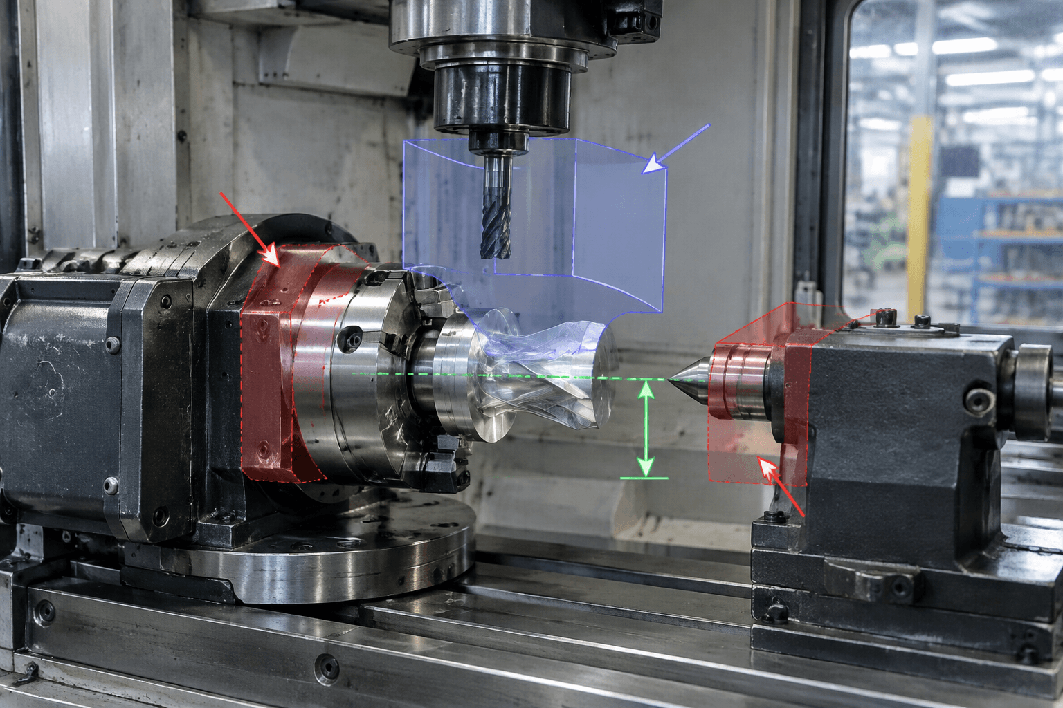
Travel and swept space: A drawing’s overall dimensions are only the starting point. The mounted part, fixture, and any projecting features must fit while the table rotates. The tool and spindle also need room to approach every planned cut. A long part may clear the machine at one angle but collide with the enclosure, spindle, or another setup component after rotation.
Rotary support and holding: Rotary-table diameter, center height, load capacity, torque, and clamping limits affect how the work can be mounted and held during cutting. A chuck or dedicated fixture occupies space and may block a feature. A tailstock can support a suitable long part, but it also consumes room and can restrict tool access. The complete mounted arrangement, including its balance and overhang, needs review against the actual machine limits.
Tooling access: A feature may face the spindle yet still be unreachable without excessive tool projection or a collision between the holder and part. Cutter diameter, holder geometry, tool length, and adjacent walls all influence the usable cutting path. Changing the part orientation or fixture may solve an access problem; otherwise, another setup or machine architecture may be needed.
Probing, coolant, and chips: If probing is planned, the probe must be able to reach useful reference features in the mounted setup. Rotary position can change how coolant reaches the cut and where chips collect. Pockets, fixtures, and enclosed features deserve particular attention when planning chip evacuation and access between operations.
Datums and inspection: Features machined at different rotary positions still need a coherent datum strategy. The drawing should identify which relationships matter, including any critical relationship between features on different faces. After milling, inspection must be able to access those features and verify them against the specified datums. Inspection confirms the result; it is not a substitute for a workable cutting setup.
Match the Geometry to the Machining Approach
The useful question is where the tool must approach each feature. The comparison below is a starting point for reviewing a drawing, not a promise that a process will complete every feature in one setup.
| Approach | Likely fit | Check before choosing |
|---|---|---|
| 3-axis milling | Features accessible from a fixed part orientation, or from a manageable number of separate setups. | Whether repositioning preserves access to the required faces and datums. |
| Indexed 4-axis milling | Multiple faces or radial features reached by turning the held part to fixed angles. | Fixture clearance, rotary holding, and whether each feature is reachable after indexing. |
| Simultaneous 4-axis milling | Features whose toolpath requires workpiece rotation during the cut. | Machine and control support, programming method, tool access, and collision clearance. |
| 5-axis milling | Features requiring an additional angular degree of freedom to orient the tool relative to the workpiece. | The specific feature approaches and machine configuration; five axes do not remove every workholding constraint. |
| CNC turning | Parts dominated by rotationally symmetric features about a central axis. | Whether off-axis holes, flats, or pockets require additional milling operations. |
A simple plate with top-face pockets may need only 3-axis milling. A housing with reachable features on several sides may justify indexing. A part with angled features that cannot be exposed by rotation about one axis may call for 5-axis milling or additional setups. If the primary geometry is a turned diameter or bore, evaluate turning separately: the workpiece rotates against a cutting tool in a different machining process.
To review a specific part, provide a drawing or CAD model, material requirement, critical features and datum references, and expected production quantity. Those details allow a geometry-led discussion of whether 4-axis milling is appropriate or another CNC machining approach should be considered. See custom CNC machining support for drawing-based parts.
Where RFQ Assumptions Create Cost and Production Risk
Many sheet metal fabrication problems begin before production starts. If drawings, tolerances, finish expectations, material grades, or assembly requirements are unclear, suppliers may quote based on different assumptions. That can make prices difficult to compare and may lead to rework, cosmetic rejection, assembly misalignment, or production delays later.
For OEM buyers, the goal is not simply to request the lowest price. The goal is to make sure each supplier is quoting the same manufacturing reality. Before confirming an order, clarify which dimensions are fit-critical, which surfaces are cosmetic, whether prototypes must match batch-production conditions, and how finished parts will be inspected.
Frequently Asked Questions
What 4 axis mill details should buyers define before requesting a quote?
Buyers should define the functional requirement, drawing notes, critical dimensions, material or process expectations, and any inspection points related to 4 axis mill. This helps suppliers quote the same manufacturing scope instead of making different assumptions.
How can RFQ details affect cost, fit, or lead time?
RFQ details can change tooling, forming, welding, finishing, inspection, or rework requirements. If buyers do not clarify it early, two supplier quotes may look comparable while covering different production risks.
Why should drawing requirements be reviewed before prototype approval?
drawing requirements may look acceptable on a single sample but become harder to control during batch production. Buyers should confirm whether the prototype reflects the same process, finish, and inspection conditions expected for production.
What inspection points matter most for 4 axis mill projects?
Important inspection points usually include fit-critical dimensions, holes or mating areas, cosmetic surfaces, finish build-up, welded or formed features, and any dimensions that affect downstream assembly. These points should appear in the RFQ or drawing notes.
How can buyers reduce prototype approval risk before batch production?
Buyers can reduce risk by clarifying drawings, locking key material and finish assumptions, defining inspection timing, approving a representative sample, and confirming which dimensions or surfaces require tighter process control.
How can Yishang help review 4 axis mill requirements?
Yishang can review drawings, RFQ notes, material requirements, tolerance expectations, finish details, samples, and assembly needs to identify unclear assumptions before quoting or batch production.