
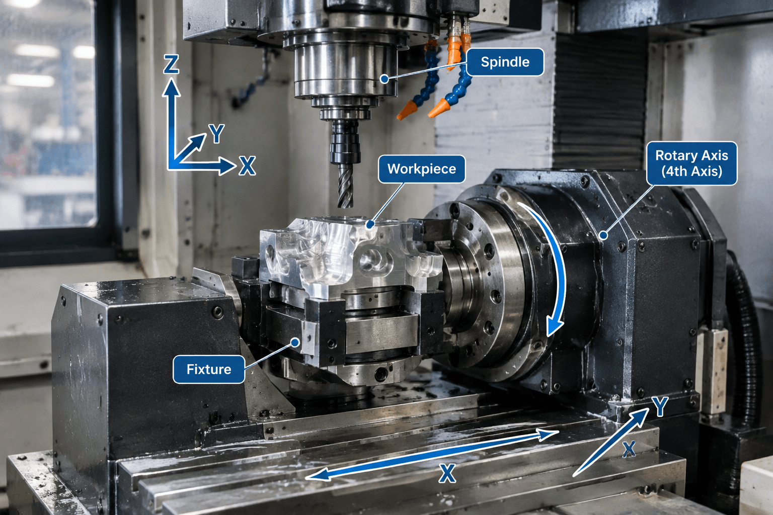
A 4 axis milling machine is a CNC milling system that combines movement along the X, Y, and Z linear axes with a controlled rotary axis. The fourth axis rotates the workpiece or fixture so the cutting tool can reach features around multiple sides, reducing the need to remove and manually reposition the part between operations.
This rotary access is useful for parts with holes, slots, flats, or profiles distributed around a cylindrical or multi-sided form. However, the actual cutting method depends on the machine architecture, controller, rotary unit, fixture, and CAM program. Some systems use the rotary axis only to index the part to a new angle, while others support coordinated rotary movement during cutting.
How the Four Axes Work Together
The first three axes define linear tool-to-workpiece movement. The X axis normally represents left-to-right travel, the Y axis represents front-to-back travel, and the Z axis represents vertical movement toward or away from the workpiece. These directions describe relative motion; depending on the machine design, the table, spindle, or both may move.
The fourth axis adds rotation, commonly identified as A, B, or C according to the linear axis around which rotation occurs. For example, an A axis rotates around X, a B axis rotates around Y, and a C axis rotates around Z. The physical orientation is not universal, so drawings, programs, and setup instructions should follow the terminology used by the machine builder.
In a typical horizontal rotary setup, a workpiece is held in a chuck, collet, fixture, or between a rotary unit and a supporting tailstock. The rotary axis turns the part to expose another surface while the milling spindle performs operations such as drilling, pocketing, contouring, or slotting. The workpiece still requires secure support, suitable tool clearance, and enough space to rotate without striking the table, fixture, spindle, or enclosure.
Rotary motion does not make the machine a lathe. In milling, a rotating cutting tool removes material from a controlled workpiece position. In turning, the workpiece normally rotates continuously while a turning tool removes material. A turned component may later receive milled flats or radial holes, but CNC turning and 4-axis milling remain distinct processes.
From One Face to the Next: A Typical Machining Sequence
Rotary access changes how multiple faces can be presented to the cutter. A simplified indexed 4-axis sequence may proceed as follows:
- Locate and secure the workpiece. The operator installs the part in a rotary fixture and establishes the required work coordinate system. The setup must control the part without blocking the features to be machined.
- Machine the first orientation. X, Y, and Z movements position the cutter for operations on the exposed face.
- Retract to a safe position. The tool moves away before rotation. The safe path must account for the fixture, workpiece projection, clamps, and nearby machine structures.
- Index the rotary axis. The workpiece turns to a programmed angle, such as the position needed to expose a side face or a radial feature.
- Clamp or hold the new position. Depending on the rotary unit, the axis may use a mechanical, hydraulic, pneumatic, or servo-controlled holding method.
- Machine the next feature group. The linear axes resume cutting at the new orientation. The sequence can repeat for additional faces.
- Inspect relevant relationships. Measurement may focus not only on individual feature size but also on angular spacing, position relative to the rotary centerline, and alignment between features on different sides.
This method is called indexed 4-axis machining, sometimes described as 3+1 machining. The rotary axis positions the part, stops, and then allows cutting with the linear axes.
In simultaneous 4-axis milling, one or more linear axes move while the rotary axis turns during the cutting pass. This can support toolpaths around a curved surface, helical features, or profiles that change with angular position. It requires suitable control functions, CAM programming, post-processing, collision review, and machine configuration. A machine advertised with a fourth axis should not automatically be assumed to support every simultaneous 4-axis operation.
Parts and Features That Benefit From Rotary Access
The main advantage of a fourth axis is controlled access around the workpiece. It is most relevant when the geometry can be presented to the spindle by rotating around one defined centerline.
| Part or feature situation | How 4-axis access may help | Important limitation or review point |
|---|---|---|
| Radial holes around a shaft, hub, or block | The part can index to each angular position without repeated manual setup. | Hole location depends on correct rotary-center alignment and secure workholding. |
| Flats on several sides | Each face can be presented to the cutter in a programmed sequence. | Clamp access, tool reach, and part stiffness still affect the setup. |
| Slots or keyways at different angles | Rotation provides consistent angular orientation between feature groups. | Deep or narrow features may remain limited by cutter geometry and chip evacuation. |
| Profiles wrapped around a cylindrical form | Simultaneous rotary motion may allow the toolpath to follow changing angular positions. | The controller, CAM system, and post-processor must support the intended motion. |
| Repeated features around a circumference | Programmed indexing can distribute features around the rotary centerline. | Feature count alone does not determine suitability; tolerances and inspection access matter. |
| Complex surfaces requiring tool tilt from several directions | A fourth axis may expose some areas. | If the tool must approach from changing angles, a 5-axis method may be more appropriate. |
A 4-axis setup is not automatically the best option for every multi-sided part. A simple prismatic component may be produced effectively on a 3-axis machine with a well-designed fixture. At the other extreme, deep cavities, undercuts, compound-angle holes, and sculptured surfaces may require access that one rotary degree of freedom cannot provide.
The rotary envelope also matters. Engineers should consider the maximum swept diameter of the loaded workpiece and fixture, not only the dimensions of the unfinished part. Long components may need tailstock or steady support, while thin sections may require fixtures that reduce deflection without obstructing the tool.
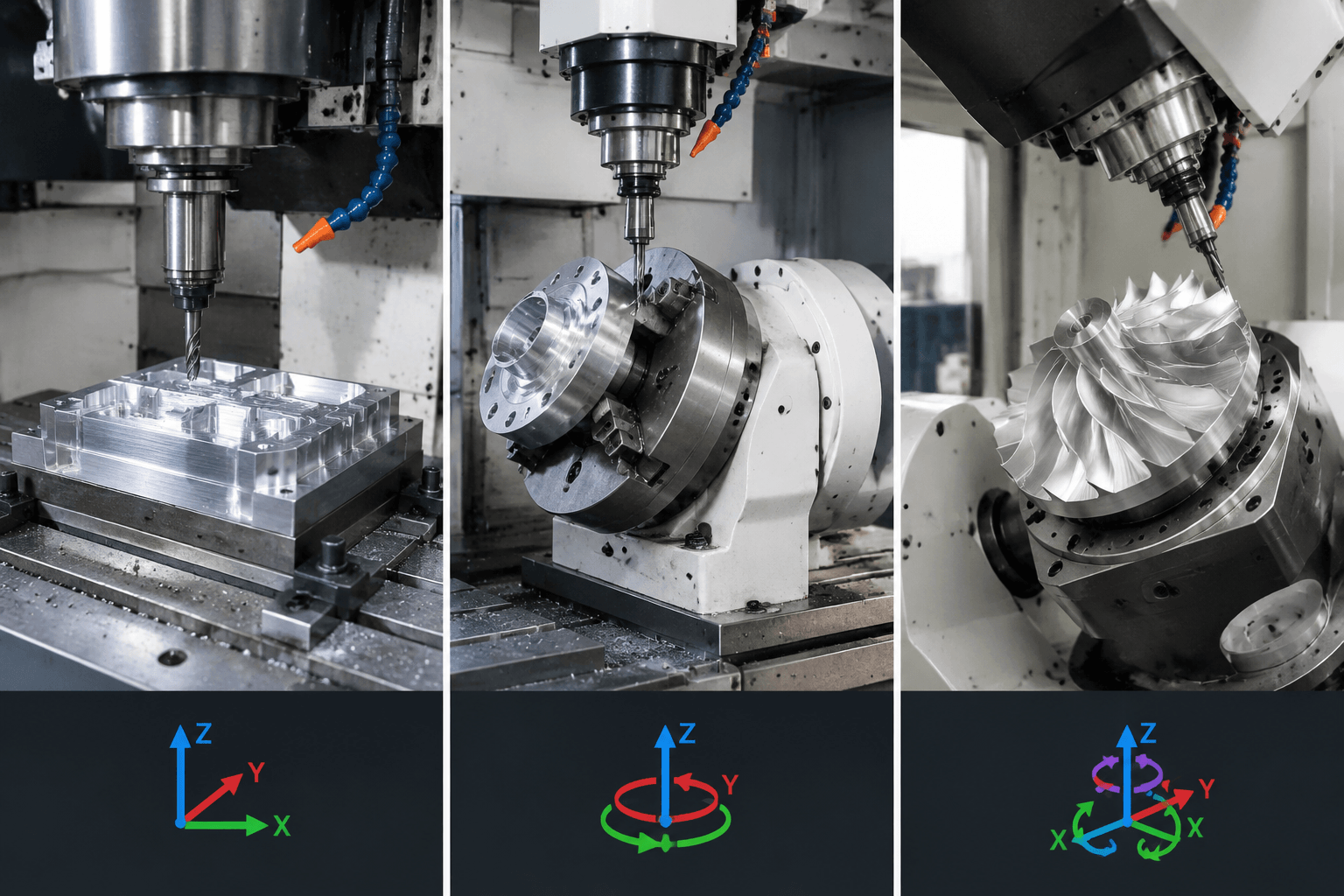
3-Axis, 4-Axis, and 5-Axis Milling Compared
Axis count indicates available controlled motion, but it does not by itself define machine quality, accuracy, capacity, or suitability. Machine architecture and control functionality must be reviewed alongside the part geometry.
| Configuration | Available motion | Typical setup implication | Geometry access |
|---|---|---|---|
| 3-axis milling | X, Y, and Z linear movement | Parts may need manual repositioning or dedicated fixtures to machine additional sides. | Well suited to features reachable from a fixed tool direction, including many pockets, holes, and planar contours. |
| 4-axis milling | Three linear axes plus one rotary axis | The part can be indexed or, where supported, rotated during cutting. | Useful for features distributed around one rotary centerline and for machining multiple presented faces. |
| 5-axis milling | Three linear axes plus two rotary axes | The tool or workpiece can be oriented from more directions, although programming and collision management become more involved. | Suitable for compound angles, complex surfaces, deep access, and geometries requiring changing tool orientation. |
Choosing between them is therefore a geometry and process-planning decision rather than a simple ranking. Four-axis milling can be a practical middle ground when one controlled rotation gives the required access. Five-axis equipment may be unnecessary for a part consisting mainly of radial holes and indexed flats, while a 4-axis machine may be insufficient when the cutter must tilt relative to the surface.
Fourth-Axis Inspection Points and Warning Signs
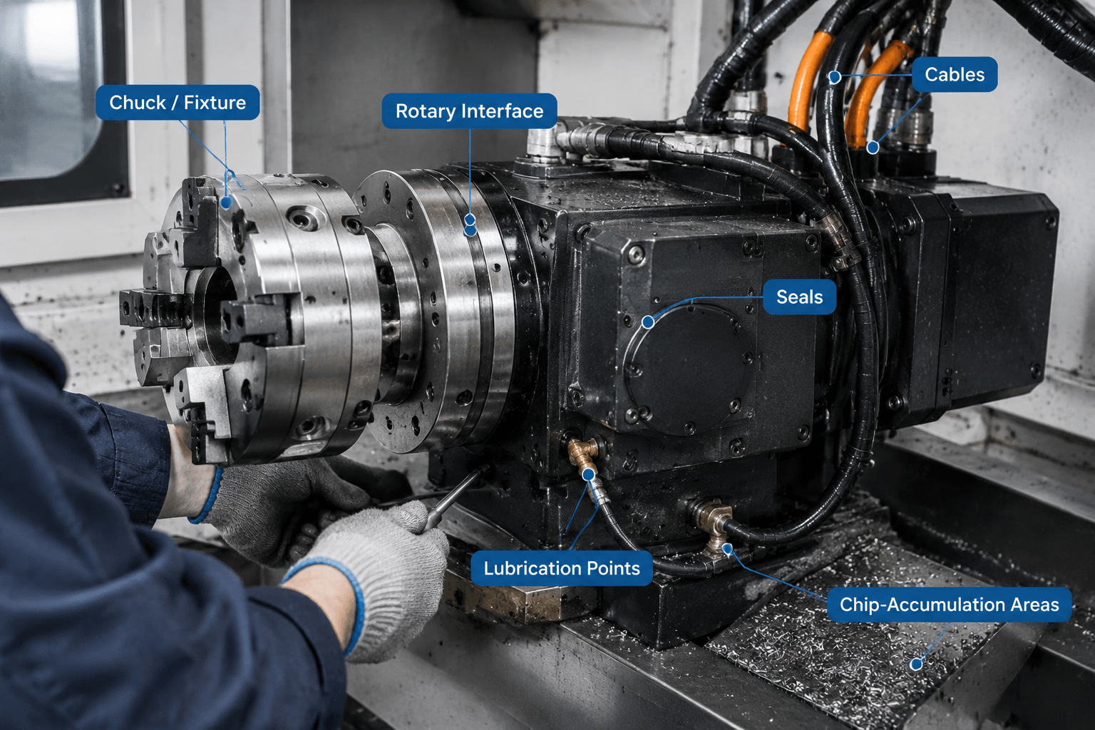
The machine builder’s manual is the authority for maintenance intervals, lubrication products, adjustment methods, acceptance limits, and corrective procedures. The following reference is an operator-level guide to observable conditions, not a replacement for OEM instructions or qualified maintenance work.
| Inspection point | What to notice | Appropriate next step |
|---|---|---|
| Rotary fixture, chuck, or clamps | Loose fasteners, damaged jaws, contamination on locating surfaces, or inconsistent clamping | Stop the setup if secure retention is uncertain. Clean and inspect components according to approved procedures. |
| Rotary interface and mounting | Visible movement, shifted locating points, impact marks, or debris beneath mounting surfaces | Do not compensate blindly in the program. Verify mounting and alignment using the prescribed method. |
| Cables, hoses, and connectors | Abrasion, tight bending, loose connections, leaks, or interference during rotation | Prevent further movement if a line could be damaged. Escalate for inspection and routing correction. |
| Seals and surrounding surfaces | Fluid leakage, damaged seals, or chips packed near rotating interfaces | Clean only as permitted and investigate the source. Avoid directing chips or high-pressure cleaning into seals. |
| Lubrication status | Warnings, low levels, contamination, or a change from normal consumption | Follow the specified lubricant and service procedure. Do not mix products without authorization. |
| Axis movement and sound | Abnormal noise, vibration, hesitation, unexpected resistance, or irregular motion | Pause operation and record when the condition occurs. Request technical evaluation before continued cutting. |
| Rotary clamping or holding | Movement during indexed cutting, inconsistent clamping indication, or finish changes at certain angles | Check the approved clamping sequence and escalate suspected loss of holding force. |
| Positioning and backlash indicators | Changing angular relationships, reversal-related position shifts, or repeated inspection drift | Confirm the measurement method, then arrange formal backlash, alignment, or calibration checks under OEM guidance. |
Operators should also watch for changes in surface pattern, burr formation, tool sound, angular feature position, and repeatability after reloading a part. These symptoms can have several causes, including the cutting tool, fixture, program, material, linear axes, or rotary unit. Troubleshooting should separate these variables rather than assuming the fourth axis is responsible.
Before discussing a project, prepare the part drawing or 3D model, material and quantity, critical features and tolerances, required finish, and relevant assembly context. A technical machining project discussion can help confirm whether the part geometry requires 3-axis milling, indexed rotary access, or simultaneous 4-axis motion and identify the information needed for production planning.
Frequently Asked Questions
What is the difference between a 4-axis milling machine and a 4-axis CNC lathe?
A 4-axis milling machine uses a rotating cutter with three linear axes and an additional controlled rotary axis. A CNC lathe is based on turning, where the workpiece normally rotates as a stationary or driven tool removes material. Some lathes include live tooling and additional axes, but their process architecture remains different from that of a milling machine.
Does a 4-axis milling machine always cut with all four axes moving simultaneously?
No. Many operations use indexed positioning: the rotary axis moves to an angle and stops before cutting begins. Simultaneous cutting requires compatible machine controls, rotary hardware, CAM programming, and post-processing. Actual capability must be confirmed for the specific equipment.
When is 4-axis milling more suitable than 5-axis milling?
Four-axis milling may be suitable when the required features are arranged around one rotary centerline and do not need continuously changing tool tilt. Examples include indexed flats, radial holes, and circumferential feature patterns. Five-axis access becomes more relevant for compound angles, complex surfaces, or obstructed areas requiring a second rotary direction.
How much does a 4-axis CNC machine cost, and what affects the price?
There is no single representative price. Cost varies with machine size, construction, rotary-unit type, controller, simultaneous-motion capability, spindle configuration, probing, tooling, workholding, software, installation, service support, and regional market conditions. Buyers should compare the required part envelope and motion functions rather than relying only on axis count.