
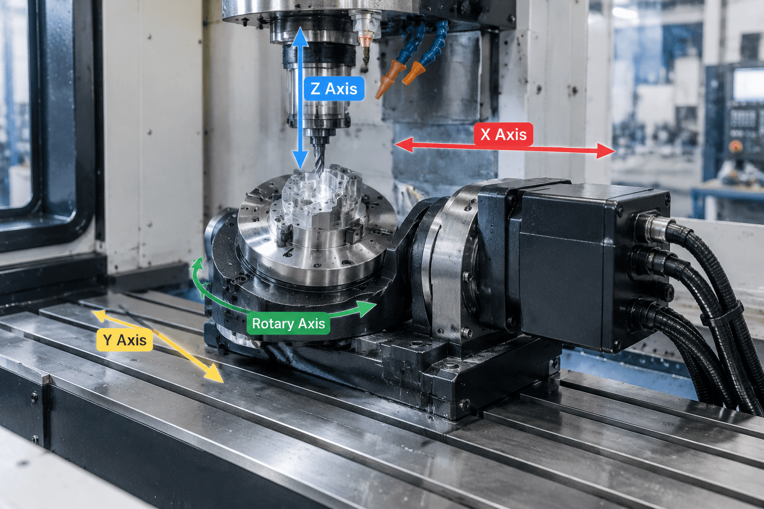
A 4 axis rotary table is a machine-tool accessory that adds controlled rotation around one axis, allowing a CNC mill to position or machine different sides of a workpiece. It is not the same as a complete four-axis CNC machine: the table is the rotary component, while true four-axis capability also depends on the machine structure, controller, drive system, software, and successful integration.
For example, consider a rectangular housing that requires holes on four sides. A three-axis machine may require the operator to stop, release, reposition, and re-establish the workpiece for each side. With a correctly integrated rotary table and suitable fixture, the control can rotate the part to defined angular positions while keeping it in one coordinated setup.
What the Fourth Axis Does During Machining
A conventional three-axis machining center moves the cutting tool or workpiece along the linear X, Y, and Z axes. A rotary table introduces angular movement, commonly identified as the A, B, or C axis according to the direction of rotation relative to those linear axes. The naming convention must be confirmed from the machine builder or control documentation rather than assumed from the table orientation alone.
Rotary operation generally falls into two categories:
- Indexed positioning: The table rotates to a specified angle and locks or holds its position before cutting begins. Machining occurs while the rotary axis is stationary. This is useful for holes, pockets, slots, or faces distributed around a part.
- Simultaneous rotary motion: The rotary axis moves in coordination with one or more linear axes while the tool is cutting. This can produce continuous features such as helical paths, wrapped profiles, or changing contours, provided the machine, controller, drive, and CAM system support coordinated motion.
This distinction matters when comparing equipment. A table capable of commanded rotation does not automatically make every three-axis mill suitable for simultaneous four-axis machining. Some installations support indexing only, while others require an external controller or operate outside the CNC’s normal coordinated-axis functions. The intended motion should therefore be defined before a model is shortlisted.
How Mounting Arrangements Change Machining Access
Rotary tables can be arranged in several ways, and orientation affects the accessible faces, fixture design, work envelope, and direction of cutting loads. The following comparison describes common arrangements rather than universal product categories.
| Configuration | Typical part position | Access pattern | Points to check |
|---|---|---|---|
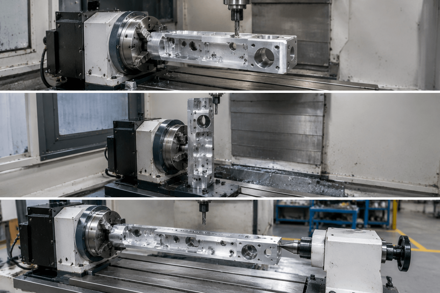
| Horizontal table | The table face is parallel to the machine table, with the rotary axis generally vertical. | Suitable for angular positioning around a vertical axis, circular patterns, and multi-station fixture layouts. | Overall height, spindle reach, fixture diameter, payload, and interference with guarding or tool changes. |
| Vertical table | The table face is upright, with the rotary axis generally horizontal. | Allows the workpiece to rotate like a part held between headstock and tailstock positions, exposing features around its circumference. | Axis center height, chuck or fixture projection, tool clearance, and bending loads from unsupported parts. |
| Vertical table with tailstock | A long workpiece is held at the rotary end and supported at the opposite end. | Useful for shafts, long prismatic parts, or components requiring indexed features along several angular positions. | Center alignment, part deflection, support pressure, fixture rigidity, and usable travel after both units are installed. |
| Tilting or trunnion arrangement | The workpiece can be presented at an inclined angle; some systems include another controlled rotary axis. | Provides access to angled faces or more complex orientations. | Whether tilt is manual or CNC-controlled, the number of actual controlled axes, machine clearance, payload, and controller support. |
A tilting arrangement requires careful terminology. A single-axis rotary table mounted at a fixed angle still provides one controlled rotary axis. A unit with two independently controlled rotary movements may form part of a five-axis or 3+2 configuration, depending on how the machine and control use those axes.
Parts and Features That Benefit From Rotary Positioning
The strongest applications are usually defined by machining access rather than by industry name. Rotary positioning is valuable when several features share a relationship around an axis or when multiple faces should be machined without repeatedly removing the part from its fixture.
Features around a circumference
Radial holes, flats, grooves, slots, keyways, pockets, and repeated patterns around cylindrical or near-cylindrical components are common candidates. A hypothetical coupling body, for instance, might require equally spaced radial holes. The table can index the part to each angle while the cutting tool approaches from a consistent direction.
Multiple faces of a prismatic component
Valve bodies, brackets, instrument housings, and compact machine components may need work on three or four sides. A rotary setup can provide access to these faces while preserving their relationship to a common datum. Whether this reduces setup variation depends on fixture rigidity, datum strategy, machine condition, and inspection planning.
Continuous or wrapped toolpaths
When simultaneous motion is available, the machine may follow a path around a rotating part instead of machining isolated angular positions. Potential applications include helical features, engraving around a cylinder, or contours that transition across the circumference. These operations require compatible CAM programming and a post-processor configured for the actual machine kinematics.
When a rotary table may not be the right approach
A rotary table is not necessary for every part. Standard three-axis milling can remain more efficient when all required features are accessible from one direction. CNC turning may be more appropriate when the component is predominantly rotational and most material removal follows the centerline. Parts requiring complex undercuts, compound angles, or continuously changing tool orientations may instead require a different machine configuration.
How to Read Rotary-Table Specifications
Specifications should be interpreted as a connected system. A large faceplate does not by itself confirm that the table can support a particular setup, and a fine command increment does not establish the achievable accuracy of the finished part.
| Specification | What it describes | Application question |
|---|---|---|
| Table, faceplate, or chuck size | The nominal workholding interface or available mounting area. | Will the intended chuck, fixture, fasteners, and part fit without creating tool or guard interference? |
| Load capacity | The permitted mass or load under stated mounting and operating conditions. | What is the combined mass and center of gravity of the part, fixture, chuck, adapters, and supports? |
| Allowable cutting or moment load | The force or moment the unit is designed to resist under specified conditions. | Do part overhang, tool engagement, and cutting direction create loads beyond the relevant rating? |
| Rotational speed | The permitted rotary speed, usually subject to load and duty conditions. | Is the operation simple indexing, continuous interpolation, or rotation during a machining cycle? |
| Minimum command or indexing increment | The smallest angular command the control can request. | Is this being confused with positioning accuracy? A small command increment does not guarantee equally small positioning error. |
| Indexing accuracy | How closely the achieved angular position agrees with the commanded position across the specified range and test conditions. | How does angular error translate into linear feature error at the part’s working radius? |
| Repeatability | How consistently the table returns to the same commanded position during repeated moves. | Does the application depend mainly on returning to known stations, or on absolute angular location across many positions? |
| Clamping or braking method | How the axis is held against movement during cutting. | Is clamping automatic, and can it be coordinated with the machining program? |
Accuracy and repeatability are related but not interchangeable. A table could return consistently to a position while retaining a systematic offset from the commanded angle. Conversely, acceptable absolute positioning over the full rotation does not reveal how closely repeated moves cluster at one station. Buyers should review the manufacturer’s test method, load condition, mounting orientation, compensation status, and measurement basis.
Match the Rotary Table to the Machine, Control, and Part
Compatibility should be checked as a sequence. Starting with a price or nominal table diameter can lead to a unit that physically fits the machine table but cannot be controlled, cleared by the spindle, or used with the intended workholding.
- Define the machining motion. State whether the process needs discrete indexing, simultaneous interpolation, or a mixture of both. Include the number of angular positions, expected cutting directions, and whether the axis must clamp during machining.
- Map the complete setup envelope. Combine the dimensions of the rotary unit, base, chuck or fixture, workpiece, tailstock, adapters, and required tool approach. Check X, Y, and Z travel as well as spindle, toolholder, enclosure, door, probe, and tool-change clearance.
- Review the mounting interface. Compare the CNC table slots or mounting holes with the rotary-table base. Confirm orientation, locating method, axis center height, fastener access, and whether an intermediate plate is necessary.
- Calculate the installed load. Include every item carried by the machine table. Rotary-table capacity and machine-table payload are separate limits, and both may be affected by load position and center of gravity.
- Confirm controller and drive integration. Identify the CNC controller, available axis channels, compatible motor and feedback requirements, amplifier capacity, parameter access, safety interlocks, and any external control arrangement. Do not assume a controller supports an additional coordinated axis merely because the machine has an available connector.
- Check cables and utilities. Determine routing and connection requirements for electrical power, feedback cables, air, hydraulics, lubrication, or coolant protection where applicable. Cables must remain clear throughout machine and rotary motion.
- Verify programming support. Confirm that the CAM system, machine definition, post-processor, axis direction, rotary limits, and unwinding behavior match the installed configuration. A trial program should be reviewed for unexpected reversals, overtravel, and collisions.
- Plan workholding and inspection. Define datum surfaces, chucking or fixture locations, tailstock use, part distortion risks, probing access, and how angularly related features will be measured.
Compatibility matrix for an initial technical review
| Area | Information to collect | What it helps determine |
|---|---|---|
| Machine | Model, table layout, travels, payload, spindle position, enclosure, and dimensional drawing | Physical installation and usable machining envelope |
| Control | Controller identification, available axis functions, drive arrangement, feedback type, and interface documentation | Indexing or simultaneous-motion feasibility |
| Rotary unit | Outline drawing, center height, mounting pattern, mass, rated loads, speed, clamping, accuracy, and repeatability conditions | Mechanical fit and performance comparison |
| Workholding | Chuck, faceplate, fixture, tailstock, adapters, locating scheme, and combined mass | Rigidity, loading, alignment, and clearance |
| Part | Drawing or 3D model, material, quantity, critical features, tolerances, and inspection requirements | Whether rotary machining is appropriate and how the setup should be planned |
| Programming | CAM system, post-processor, indexing logic, simultaneous toolpaths, and axis limits | Whether programmed motion matches actual machine behavior |
For a meaningful comparison, request dimensional drawings and integration documents rather than relying on a product photograph or model name. Total cost may also involve adapters, workholding, control hardware, installation, post-processor work, training, maintenance, and spare parts; these items vary by supplier and application.
Frequently Asked Questions
What is the difference between a rotary table and a complete 4 axis CNC machine?
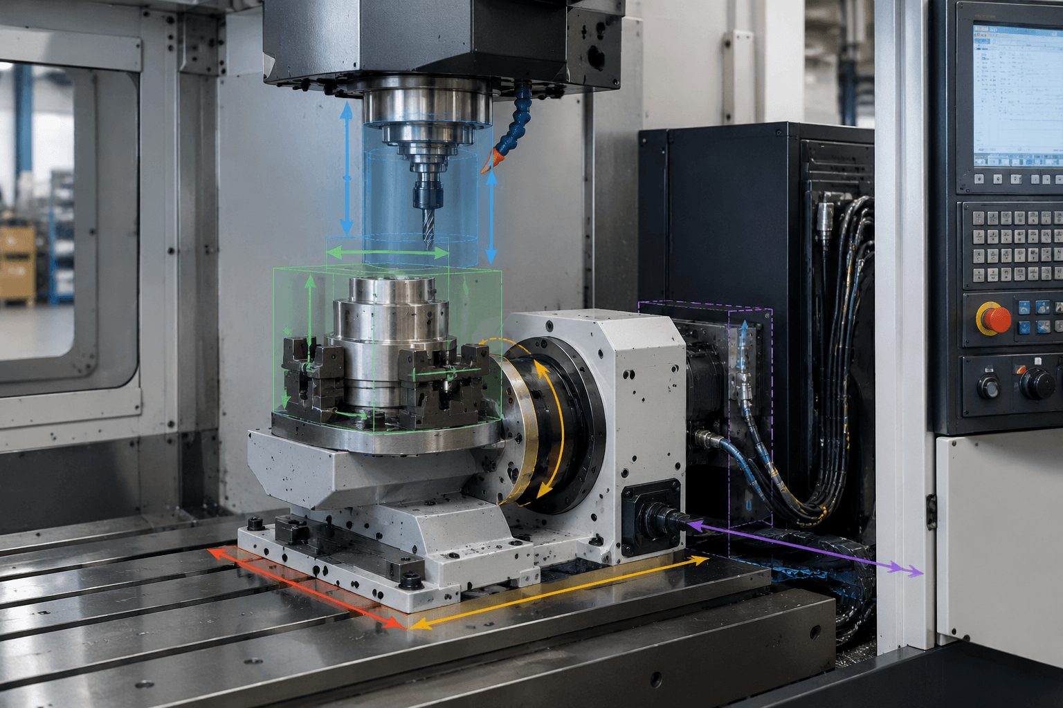
A rotary table is the mechanical unit that rotates and holds the workpiece. A complete four-axis CNC configuration also includes compatible machine structure, axis drive, feedback, controller functions, cabling, safety logic, programming, and workholding. Installing the component alone does not confirm coordinated four-axis capability.
Can a rotary table be added to any three-axis CNC mill?
No. Compatibility depends on table payload, mounting space, travel, center height, spindle and enclosure clearance, controller capacity, drive and feedback requirements, utilities, software, and safe cable routing. Some machines may support only externally controlled indexing, while others may not be suitable for an additional rotary axis.
What is the difference between indexing accuracy and repeatability?
Indexing accuracy describes how closely the actual angular position matches the commanded position under stated test conditions. Repeatability describes how consistently the table returns to the same position. Both should be evaluated separately and translated into the resulting feature-location effect at the workpiece radius.
When is a 4 axis rotary table preferable to manually repositioning the workpiece?
It may be preferable when a part has related features on multiple faces or around a common axis and those features can be reached in one stable setup. The practical benefit depends on setup time, fixture rigidity, part geometry, production quantity, programming requirements, inspection strategy, and the machine’s integrated rotary capability.