

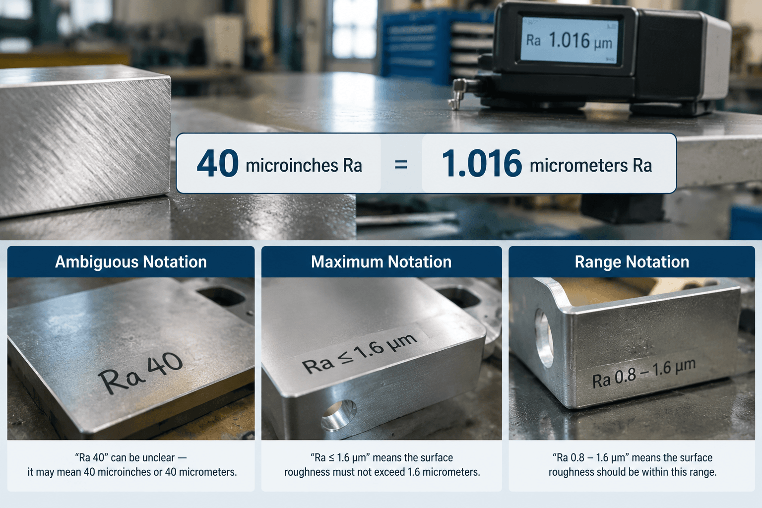
In many US manufacturing contexts, a 40 surface finish means 40 microinches Ra, equal to 1.016 micrometers Ra, but the drawing must state both the roughness parameter and the unit. The number 40 alone is ambiguous because it could refer to a different unit, roughness parameter, or shop-specific finish description.
Conversion: 40 microinches × 0.0254 = 1.016 micrometers, commonly rounded to approximately 1.0 micrometer Ra.
Ra is the arithmetic average of profile deviations from a mean line over a defined measurement setup. It is useful for quantifying fine surface texture, but it does not by itself describe waviness, lay, isolated defects, visual appearance, or suitability for a particular application.
Interpreting 40 Surface Finish on a Drawing
The first step is to determine what the designer intended by the shorthand. A value written as 40 microinches Ra maximum has a clear upper limit. A note that says only 40 finish does not.
| Drawing or order notation | Likely interpretation | What requires clarification |
|---|---|---|
| 40 finish | Often interpreted in US practice as 40 microinches Ra | Parameter, unit, limit type, applicable surface, and measurement conditions |
| Ra 40 microinches max | No measured Ra value may exceed 40 microinches at the defined inspection locations | Measurement setup, direction, reading count, and any separate defect criteria |
| Ra 20-40 microinches | Measured Ra must remain within a bounded range | Whether every reading or an agreed statistical result must satisfy the range |
| Ra 40 micrometers | A much rougher numerical requirement than 40 microinches Ra | Confirm that micrometers, rather than microinches, are intentional |
| Rz 40 | A different roughness parameter | Unit, measurement conditions, and the applicable definition of Rz |
| 40 grit | An abrasive designation, not a measured Ra value | Required final roughness, appearance, direction, and defect limits |
A maximum requirement and a range serve different purposes. With Ra 40 microinches max, smoother measured values generally satisfy the numerical limit unless another requirement says otherwise. With Ra 20-40 microinches, a surface below 20 microinches is also outside the specified range. A bounded range may be used when texture is functionally relevant, but its suitability depends on the part and application.
Do not convert Ra automatically into RMS, Rz, CLA, or another parameter. Relationships among parameters depend on the surface profile, filtering, measurement method, and parameter definitions. A numerical shortcut cannot establish equivalence for every manufactured surface.
How to Measure a 40 Microinch Ra Requirement
Comparable readings require comparable measurement conditions. A contact profilometer traces the surface with a stylus and processes the measured profile, but the displayed Ra can change when the setup changes. The inspection plan should therefore define more than the target number.
- Identify the inspection area. Mark the controlled face or zone on the drawing. State whether edges, weld transitions, holes, bends, and interrupted surfaces are included or excluded. A stylus may not be able to traverse a narrow or discontinuous area reliably.
- Set the cutoff and filtering. The selected cutoff and filter separate roughness information from longer-wavelength form and waviness. Different settings can produce different results on the same physical surface, so the agreed setup or governing specification should be referenced.
- Define sampling and evaluation length. Ra is evaluated over a prescribed profile length rather than at a single point. The selected length must suit the surface texture and available measurement area.
- Control probe direction. Measurements are commonly taken across the predominant lay because a trace parallel to machining or abrasive marks can report a different value. If direction matters, show it on the drawing or inspection note.
- Specify locations and reading count. State how many readings are required and where they are taken. This is especially important for large panels, locally polished areas, or surfaces affected by several manufacturing operations.
- Confirm instrument condition. Stylus condition, instrument verification or calibration status, fixture stability, cleanliness, and part temperature can affect confidence in the result. Inspection records should identify the instrument and relevant setup details.
Machining feed, tool condition, vibration, material, and geometry can influence the generated texture. Abrasive type, tool pressure, abrasive wear, lubrication, and travel direction can also change the result. Neither route guarantees a particular Ra without process control and measurement; the manufacturing method and the measurable finish requirement should still be specified separately.
Ra Does Not Describe the Entire Surface
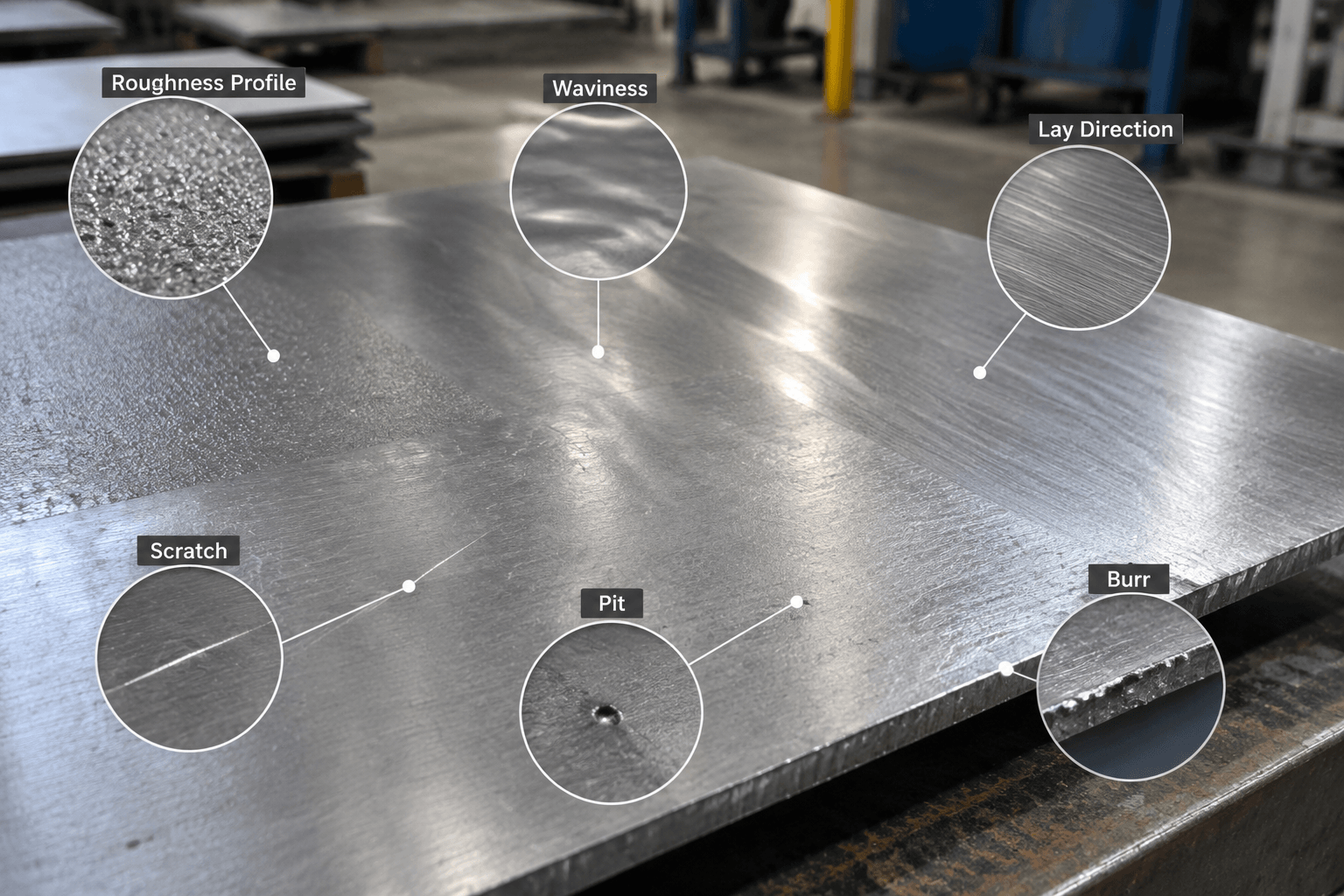
A component can meet 40 microinches Ra at the measured locations and still be unacceptable for its intended use. Ra averages profile deviations, so it may not adequately represent long waves, directional texture, or an isolated defect.
| Surface characteristic | What it describes | How to control it |
|---|---|---|
| Roughness | Fine, closely spaced surface irregularities evaluated with a defined roughness parameter | State Ra or another required parameter, units, limits, and measurement setup |
| Waviness | More widely spaced surface variation that may come from distortion, vibration, or process conditions | Use an appropriate waviness, flatness, or form requirement when function demands it |
| Lay | The predominant direction of the surface pattern | Show the required lay direction and probe direction where relevant |
| Scratch or pit | A localized groove or depression | Add visual acceptance criteria, size limits, or an approved reference where needed |
| Burr or fold | Raised or overlapping material, often near an edge or process transition | Specify edge condition and prohibit unacceptable folded or loose material |
| Inclusion or embedded contamination | Foreign or nonuniform material within or on the surface | Define material, cleanliness, and visual inspection requirements separately |
| Cosmetic appearance | Color, gloss, reflectivity, uniformity, and visible directional pattern | Use appearance criteria, viewing conditions, finish samples, or approved limit samples |
This distinction matters on product-contact, sealing, sliding, coating, and visible surfaces. A specified Ra value alone does not guarantee cleanability, hygiene, corrosion resistance, coating adhesion, sealing performance, or appearance. Those outcomes also depend on material, geometry, fabrication details, finishing sequence, service conditions, and application-specific acceptance requirements. Product-contact fabrication may require separate attention to joints, edges, product-contact zones, and visible defects in addition to measured roughness.
Write a Complete Surface-Finish Note
A useful requirement identifies what is measured, where it applies, how acceptance is determined, and which conditions are controlled separately. The following is a generic example, not a universal specification:
Specified surfaces A: Ra 40 microinches maximum (1.016 micrometers maximum). Measure perpendicular to the predominant lay using the cutoff, filter, and evaluation length defined in the approved inspection method. Take three readings at the locations shown. Exclude edge breaks and interrupted regions. Surfaces shall be free from burrs, folds, embedded abrasive, and scratches exceeding the separate visual acceptance criteria.
The fields in this example serve different purposes:
- Parameter: Ra identifies the roughness metric.
- Unit: Microinches, with a metric equivalent, prevents a 40-microinch versus 40-micrometer misunderstanding.
- Limit type: “Maximum” means the stated value is an upper limit, not a nominal target or range.
- Applicable area: A marked surface prevents inspection of an unrelated face.
- Measurement direction: The probe travels perpendicular to the predominant lay.
- Evaluation setup: The approved method defines cutoff, filtering, and evaluation length.
- Reading plan: The note defines the count and refers to controlled locations.
- Defect expectations: Burrs, folds, embedded material, and scratches are addressed separately from Ra.
If both a lower and upper value are required, replace the maximum-only limit with a bounded statement such as Ra 20-40 microinches. The drawing should also state whether every reading must fall within that range or whether another acceptance method applies. Do not add a lower limit merely to make the note look complete; use it only when the surface function requires a controlled texture band.
Grit size and polishing labels can remain as process instructions when they are genuinely needed, but they should not replace the measured requirement. The Ra produced by a particular abrasive varies with material, starting condition, pressure, speed, abrasive wear, lubrication, tool path, and subsequent processing. Likewise, a visual description such as “satin” or “mirror” needs a separate appearance reference because surfaces with similar Ra values can look different.
Frequently Asked Questions
Is 40 surface finish the same as 40 Ra?
Not automatically. In many US manufacturing contexts, “40 finish” is shorthand for 40 microinches Ra, but the notation is incomplete unless it states Ra and microinches. Confirm the parameter, unit, limit type, applicable area, and measurement conditions before manufacturing or inspection.
What is 40 microinch Ra in micrometers?
It is 1.016 micrometers Ra because one microinch equals 0.0254 micrometer. Drawings may round this to about 1.0 micrometer Ra, but inspection limits should use consistent units and agreed rounding so that conversion does not create conflicting acceptance decisions.
What grit produces a 40 Ra finish?
There is no universal grit-to-Ra equivalence. The result depends on the alloy, starting surface, abrasive system, pressure, speed, abrasive condition, lubrication, stroke direction, and later finishing steps. Specify the measured Ra requirement separately, then validate the selected process on representative material and geometry.
How does about 1.0 micrometer Ra compare with 1.6, 0.8, or 0.4 micrometer Ra?
Numerically, 1.6 micrometers Ra is rougher and 0.8 or 0.4 micrometer Ra is smoother in arithmetic-average terms than approximately 1.0 micrometer Ra. These values are not functionally interchangeable. The appropriate limit depends on the surface’s role, and similar Ra values can still have different lay, waviness, defects, and appearance.