
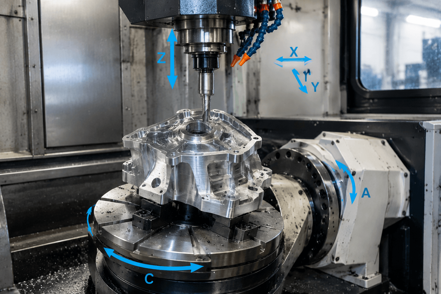
5-axis machining uses three linear axes and two rotary or tilting axes to position a cutting tool and workpiece from multiple directions. In practical terms, it can provide access to angled holes, several faces, deep cavities, and changing surfaces that may be difficult to reach with a conventional 3-axis setup. The key distinction is between indexed 3+2 machining, where the rotary axes position the workpiece or tool before cutting, and simultaneous 5-axis machining, where linear and rotary axes move together during the cut. Indexed 3+2 is often suitable for discrete angled features and multiple faces; simultaneous motion is used when the tool orientation must change continuously along a surface or toolpath.
What Does 5-Axis Machining Mean?
A standard 3-axis machining center moves the cutting tool or workpiece along three linear directions:
- X axis: movement from side to side.
- Y axis: movement from front to back.
- Z axis: movement up and down, commonly associated with tool approach and depth.
A 5-axis machine adds two rotary or tilting axes. These may rotate the workpiece, tilt the cutting head, or combine both actions. The rotary axes may be identified with letters such as A, B, or C, but the exact designation depends on which linear axis the rotary motion references and how the machine is configured. The same machining objective can therefore be achieved with different physical layouts.
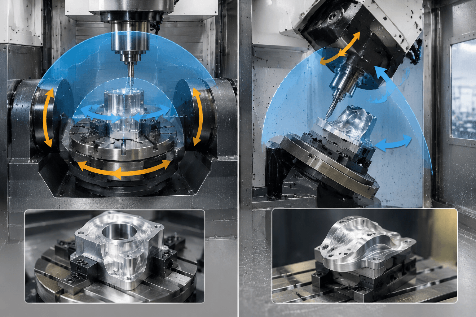
In a trunnion or rotary-table machine, the workpiece is mounted on a table that rotates and tilts. In a swivel-head machine, the cutting head changes orientation while the workpiece may remain on a fixed table. Other machines combine a tilting head with a rotary table. These arrangements are not interchangeable for every job because they affect work envelope, part loading, payload, tool reach, rigidity, and collision clearance.
The added axes do not automatically make every job better suited to 5-axis machining. The decision depends on the part geometry, required access, tolerances, surface strategy, production quantity, workholding plan, and the capability of the complete programming and inspection process.
3+2 Positioning Compared With Simultaneous 5-Axis Motion
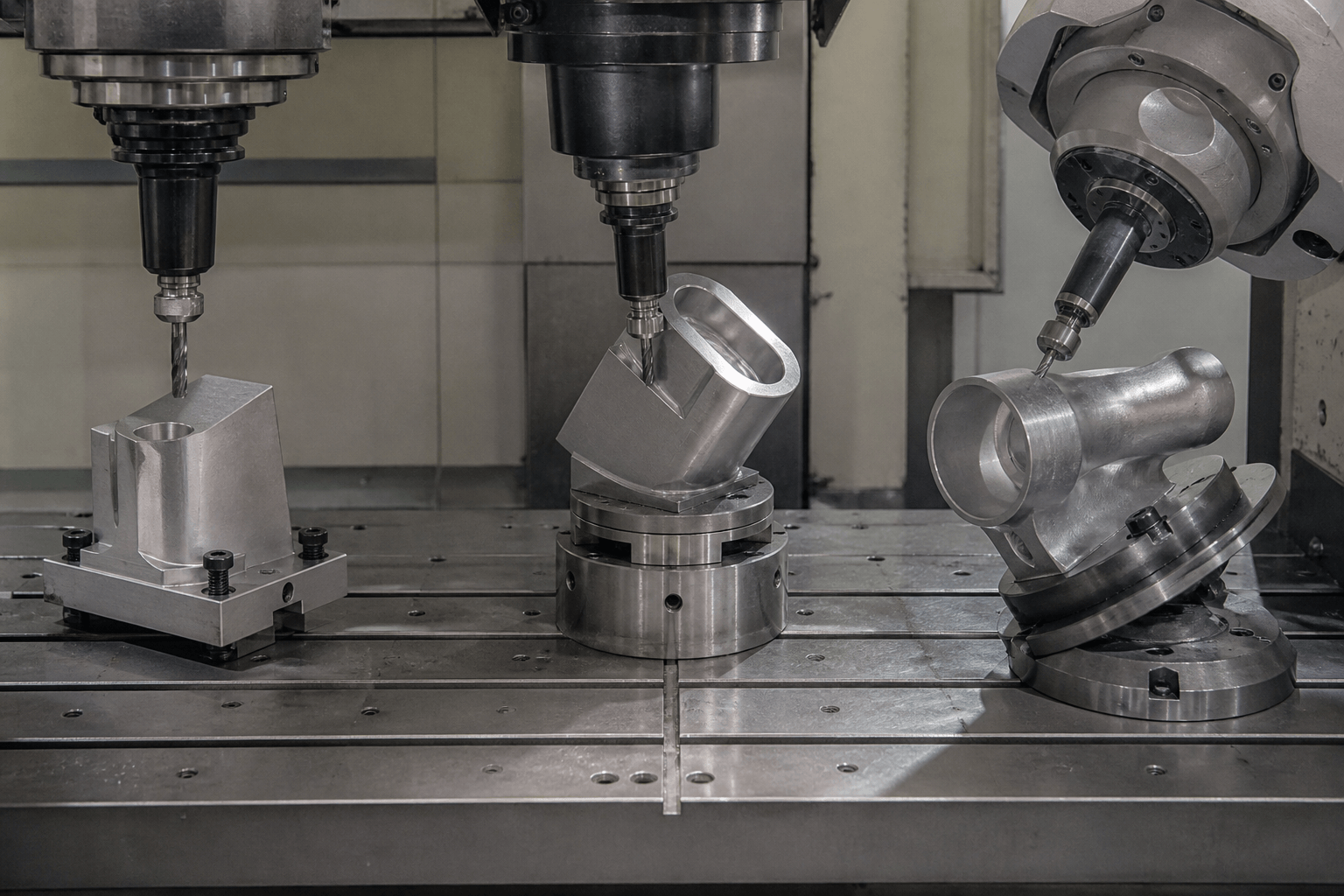
Both methods use five machine axes, but they control those axes differently. In indexed 3+2 machining, the rotary axes move the tool or workpiece to a selected orientation and then remain stationary while the cutting operation takes place. The machine can be repositioned for another face or angle. In simultaneous 5-axis machining, the rotary and linear axes can move together while the tool follows the programmed path.
| Consideration | Indexed 3+2 machining | Simultaneous 5-axis machining |
|---|---|---|
| Tool orientation | Set to a fixed angle for each machining orientation. | Can change continuously during the toolpath. |
| Typical geometry | Angled holes, features on multiple faces, and pockets reachable from defined directions. | Continuously changing surfaces, compound contours, and areas requiring sustained tool-orientation control. |
| Setups and repositioning | May reduce physical re-fixturing, but still requires multiple indexed orientations and verification. | Can support a continuous toolpath across suitable geometry, subject to machine travel and collision limits. |
| Programming requirement | Requires correct workplane definitions, tool orientation, and postprocessor output for each index. | Requires more extensive tool-axis planning, postprocessing, simulation, and collision checking. |
| Decision basis | Often appropriate when the part has discrete access directions and the cutting tool can remain fixed during each operation. | Appropriate when the surface or access requirement changes continuously along the cut. |
For example, a component with holes drilled at several fixed angles may be a good candidate for indexed 3+2 work. A contoured component with a surface that changes direction across the toolpath may require simultaneous motion to maintain the intended tool orientation. A deep cavity could benefit from a tilted approach, but that does not by itself mean that simultaneous 5-axis machining is necessary.
Geometry and tolerance requirements should be reviewed together. A part may be reachable with 3+2 positioning but still require additional finishing operations, workholding changes, or inspection planning. Conversely, a complex-looking model may be efficiently machined with indexed orientations if its critical features are accessible from a limited number of fixed directions.
Machine Configurations and Part-Access Tradeoffs
Trunnion or rotary-table arrangement
A trunnion-style machine supports the workpiece on a rotary and tilting structure. This can provide useful access around several sides of a part and may simplify tool orientation for angled features. The tradeoffs include the available table space, part height, payload, rotary range, and the effect of the mounted workpiece on the usable work envelope. A large or heavy component can also make loading and clearance more demanding.
Workholding must account for rotary movement. Fixtures, clamps, jaws, and the part itself need sufficient clearance throughout the planned motion. The fixture must also support the part without obstructing the surfaces that require machining. For some parts, a rotary-table arrangement is practical because the workpiece remains securely supported while the table changes orientation. For others, the table and fixture may restrict access or reduce the available envelope.
Swivel-head arrangement
In a swivel-head configuration, the machine changes the cutting-head orientation around the workpiece. This can be useful when the part is large, when the table needs to remain fixed, or when tool access around a stationary workpiece is important. The machine must still provide enough head travel, rotary range, spindle clearance, and rigidity for the intended cut.
Swivel-head machines can introduce different reach and collision considerations. The head, spindle housing, holder, and tool may approach the workpiece at several angles, so the programmed motion must be checked against the part and fixture. The machine’s kinematic behavior also affects how the tool center point is controlled during rotary movement.
How to match a configuration to the part
Review the part’s overall dimensions, weight, center of gravity, critical faces, required tool reach, and workholding surfaces before choosing a configuration. A machine with five axes may still be unsuitable if the part exceeds the work envelope, interferes with the rotary structure, exceeds the payload, or requires a tool approach outside the machine’s usable range. Rigidity is also important when the process involves long tools, difficult materials, or cutting conditions that are sensitive to vibration.
Programming, Tooling, and Process Control
A 5-axis machine is only one part of the process. Reliable production also depends on CAM programming, postprocessor compatibility, simulation, tooling, workholding, setup, and operator experience.
CAM strategy: The programmer must select appropriate toolpaths, tool orientations, lead and tilt angles, linking moves, and entry or exit strategies. The strategy should reflect the actual machine kinematics and the surfaces that need to be protected or finished.
Postprocessor: CAM output must match the specific machine control, axis arrangement, rotary limits, and tool center point behavior. A postprocessor that is suitable for one configuration should not be assumed to be suitable for another without verification.
Simulation and collision avoidance: Simulation should account for the machine model, spindle, holder, tool, fixture, workpiece, and planned rotary motion. It can help identify collisions, axis-limit problems, unwanted tool orientation, and linking moves that are unsuitable for the actual setup. Simulation does not replace setup verification or controlled prove-out.
Tool center point control: During simultaneous movement, the machine has to maintain the programmed relationship between the cutting point and the workpiece as the rotary axes move. The control strategy and postprocessor output must support the machine’s tool center point requirements.
Tooling and holder clearance: The cutting tool, holder, spindle nose, and head housing all affect access. A short tool may improve rigidity but fail to reach a recessed surface. A longer tool may reach farther but increase deflection or collision exposure. Tool selection should therefore be based on reach, clearance, material, feature geometry, and the required cutting conditions.
These requirements illustrate the difference between nominal machine capability and a verified production process. A supplier or internal manufacturing team should confirm that the machine, software, tooling, workholding, inspection method, and operator workflow are suitable for the specific part.
When Is 5-Axis Machining a Good Fit?
5-axis machining may be worth evaluating when a part has several of the following characteristics:
- Angled holes, ports, or mounting features that are difficult to reach from one fixed direction.
- Machined faces on multiple sides of a part.
- Deep cavities or recessed areas where tool access is limited.
- Compound or continuously changing surfaces that require controlled tool orientation.
- Features whose relationship to one another makes repeated manual repositioning undesirable.
- Workholding constraints that make conventional multi-setup machining difficult to plan.
These characteristics are indicators for evaluation, not proof that 5-axis machining is the correct answer. A 3-axis process with carefully planned setups, a 4-axis approach, or another CNC method may be more appropriate for a particular part. Rotational parts may instead be better suited to CNC turning, while sheet metal fabrication, welding, finishing, and assembly remain separate processes with different equipment and process boundaries.
3+2 or Simultaneous 5-Axis? A Geometry-First Selection Matrix
| Part condition | Approach to evaluate first | Reason for review |
|---|---|---|
| Features are on several faces but each can be machined from a fixed angle. | Indexed 3+2 | Fixed tool orientations may provide the required access without continuously changing the tool axis. |
| Surface direction changes continuously along the cutting path. | Simultaneous 5-axis | Continuous rotary motion may be needed to maintain the desired tool relationship. |
| A deep feature requires a tilted approach but has no changing surface. | 3+2 or another access strategy | The feature may need only a selected orientation, subject to holder and fixture clearance. |
| Several operations require repeated manual repositioning. | Compare 3+2, simultaneous 5-axis, and conventional multi-setup workholding | The complete process should be compared, including fixturing, datum control, inspection, and programming. |
| Tight or functionally important relationships exist between features. | Evaluate the process against the required tolerance and inspection plan | Axis count alone does not establish whether the required accuracy or repeatability can be achieved. |
How to Evaluate a 5-Axis Process
- Define the geometry. Identify angled, deep, multi-face, and continuously changing features, along with the surfaces that must remain accessible for cutting and inspection.
- Review the required access. Determine whether the part needs fixed tool orientations, continuous tool-axis motion, or only a conventional multi-setup process.
- Check the machine configuration. Compare the part dimensions, weight, work envelope, axis travel, rotary range, payload, spindle performance, rigidity, and clearance against the intended operation.
- Confirm process control. Ask how CAM programming, postprocessing, tool center point control, simulation, collision checking, tooling, and prove-out will be handled.
- Plan quality requirements. Identify critical dimensions, datums, tolerances, repeatability expectations, surface requirements, and the inspection method. These requirements should be considered before selecting the machining strategy.
- Compare the complete process. Include programming, workholding, setup, inspection, secondary operations, quantity, and expected production schedule rather than comparing machine-axis count alone.
For a technical review, provide the part drawing or CAD file, material, overall dimensions, critical features, tolerances, surface-finish requirements, quantity, expected schedule, inspection needs, and any features requiring angled, deep, or multi-face access. This information allows the machining approach to be assessed against the actual part rather than a general description of 5-axis capability.
Discuss the Part Before Selecting the Process
A drawing or CAD review can help determine whether indexed 3+2 positioning, simultaneous 5-axis machining, conventional multi-setup workholding, or another CNC approach is the better fit. Share the part drawings or CAD files together with the material, critical dimensions, tolerance and surface-finish requirements, quantity, expected production schedule, and features requiring angled, deep, or multi-face access. The review should consider geometry, programming, workholding, inspection, and secondary operations as one process.
For broader context on how a custom project moves from initial sample evaluation toward repeat production, see Custom CNC Machining From First Sample to Repeat Production.
Where RFQ Assumptions Create Cost and Production Risk
Many sheet metal fabrication problems begin before production starts. If drawings, tolerances, finish expectations, material grades, or assembly requirements are unclear, suppliers may quote based on different assumptions. That can make prices difficult to compare and may lead to rework, cosmetic rejection, assembly misalignment, or production delays later.
For OEM buyers, the goal is not simply to request the lowest price. The goal is to make sure each supplier is quoting the same manufacturing reality. Before confirming an order, clarify which dimensions are fit-critical, which surfaces are cosmetic, whether prototypes must match batch-production conditions, and how finished parts will be inspected.
Frequently Asked Questions
What 5 axis details should buyers define before requesting a quote?
Buyers should define the functional requirement, drawing notes, critical dimensions, material or process expectations, and any inspection points related to 5 axis. This helps suppliers quote the same manufacturing scope instead of making different assumptions.
How can RFQ details affect cost, fit, or lead time?
RFQ details can change tooling, forming, welding, finishing, inspection, or rework requirements. If buyers do not clarify it early, two supplier quotes may look comparable while covering different production risks.
Why should drawing requirements be reviewed before prototype approval?
drawing requirements may look acceptable on a single sample but become harder to control during batch production. Buyers should confirm whether the prototype reflects the same process, finish, and inspection conditions expected for production.
What inspection points matter most for 5 axis projects?
Important inspection points usually include fit-critical dimensions, holes or mating areas, cosmetic surfaces, finish build-up, welded or formed features, and any dimensions that affect downstream assembly. These points should appear in the RFQ or drawing notes.
How can buyers reduce prototype approval risk before batch production?
Buyers can reduce risk by clarifying drawings, locking key material and finish assumptions, defining inspection timing, approving a representative sample, and confirming which dimensions or surfaces require tighter process control.
How can Yishang help review 5 axis requirements?
Yishang can review drawings, RFQ notes, material requirements, tolerance expectations, finish details, samples, and assembly needs to identify unclear assumptions before quoting or batch production.