
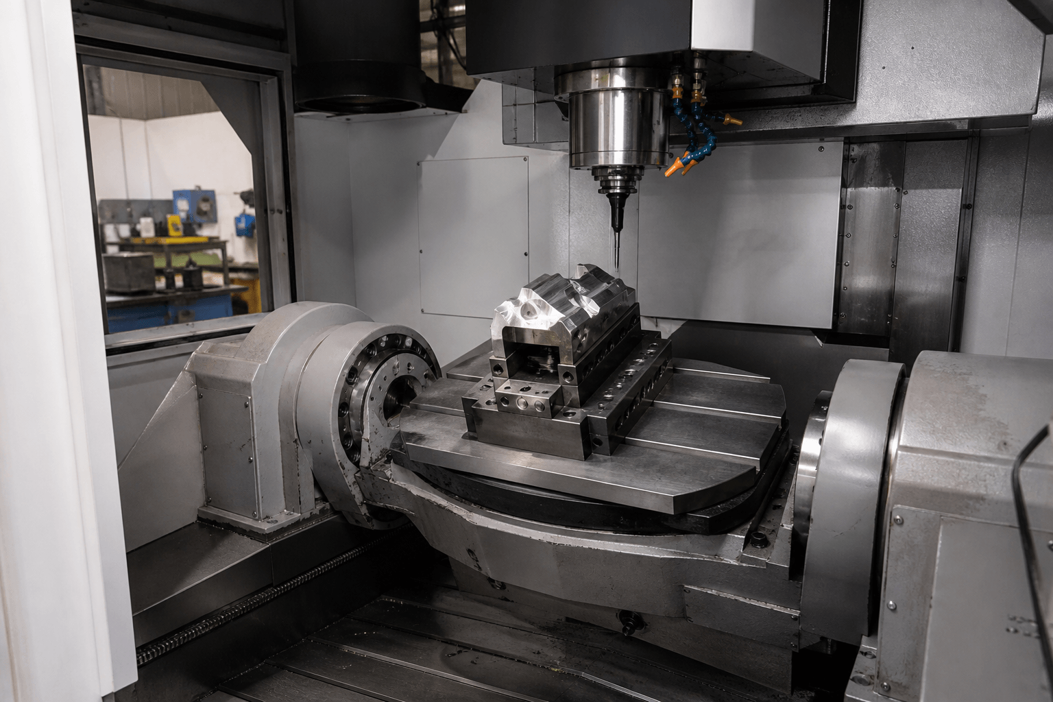
A 5 axis mill is a CNC milling machine that combines three linear axes with two rotary axes, allowing the cutting tool to approach a workpiece from changing directions. The five-axis label describes relative motion between the tool and workpiece; it does not, by itself, guarantee simultaneous movement, a particular accuracy, or suitability for every material.
The easiest way to interpret these machines is to look at their anatomy: three straight-line motions plus two rotations. Where those rotations occur—at the table, spindle head, or both—determines how the machine moves and influences access, clearance, workholding, and practical workpiece capacity.
Reading the Five Axes
The linear axes are named X, Y, and Z. In a typical milling-machine coordinate system, Z is parallel to the spindle axis in its reference orientation, while X and Y define the perpendicular working plane. Tilting the head or table changes the tool’s orientation relative to the workpiece without redefining these linear axes. The actual machine may move the table, spindle, or a combination of components, but the important point is their relative linear motion.
Rotary-axis names follow the corresponding linear axes:
- A-axis: rotation about the X-axis.
- B-axis: rotation about the Y-axis.
- C-axis: rotation about the Z-axis.
A particular 5-axis CNC mill uses only two of these three possible rotary-axis designations. For example, one machine may combine X, Y, and Z with A and C, while another uses B and C. Axis naming must therefore be checked against the manufacturer’s coordinate diagram rather than inferred from a photograph.
Conceptual axis diagram: one table-table arrangement
X ↔ left/right | Y ↔ front/back | Z ↕ along the spindle axis in its reference orientation
A ↻ table tilts about X | C ↻ table rotates about Z
Spindle → cutting tool → workpiece → fixture → rotary table
For comparison, a three-axis mill cuts using X, Y, and Z without commanded rotary positioning. The term 2.5-axis milling generally refers to operations in which two axes interpolate while another axis is positioned at a fixed level, rather than to a machine with half an axis. A four-axis machine adds one rotary axis. These terms describe motion arrangements, not an automatic ranking of part quality.
Where the Two Rotary Axes Live
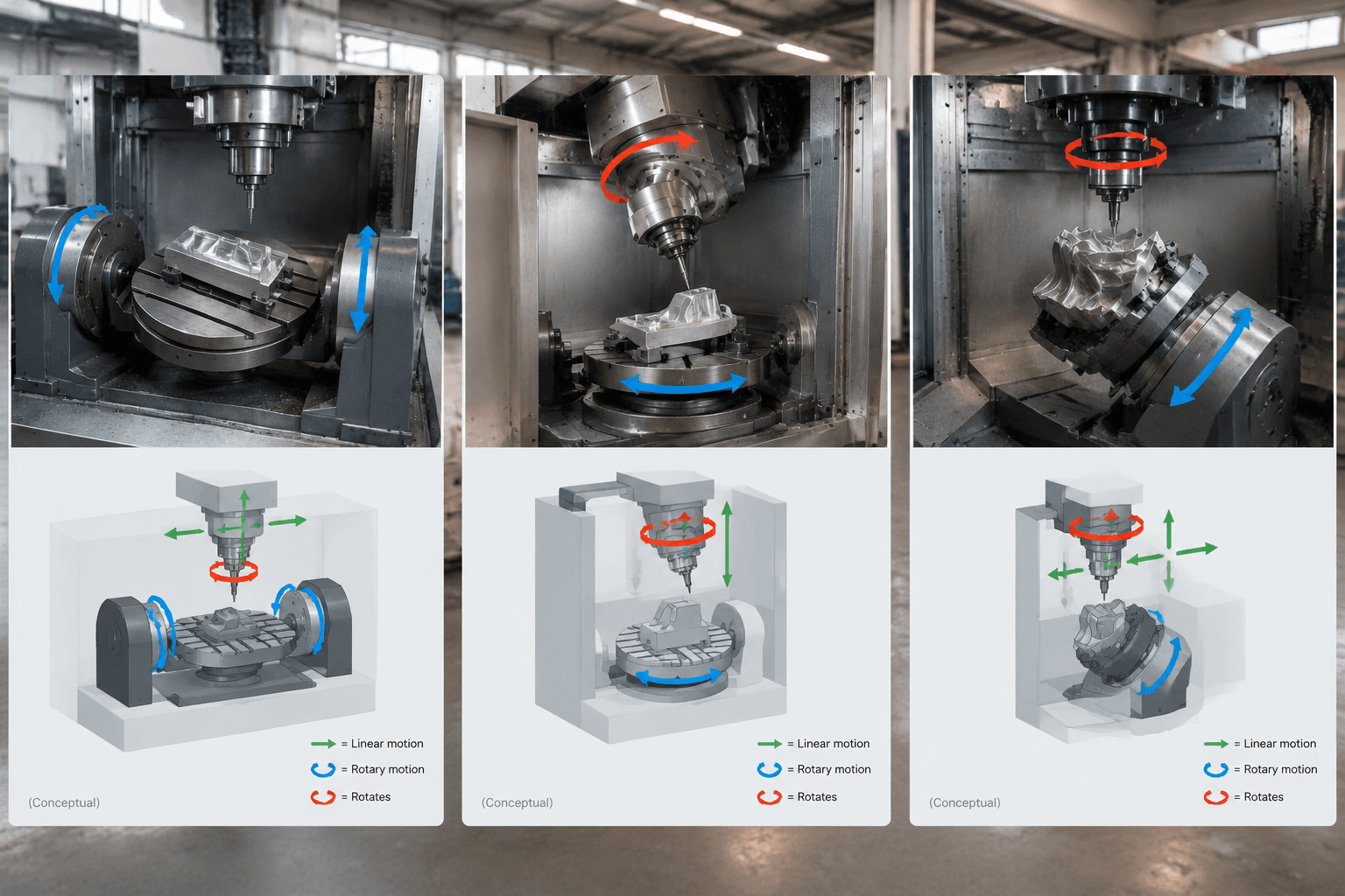
Five-axis mills can look very different because manufacturers distribute rotary movement among the table and spindle head. The three common architecture families are table-table, head-table, and head-head.
Table-table
Both rotary motions occur in the workholding table. A common arrangement is a rotary platter carried by a tilting cradle. The spindle head remains fixed in angular orientation while the fixture and workpiece tilt and rotate beneath it. Buyers should examine the usable envelope at tilted positions, the fixture’s distance from the rotary center, and possible interference between the table, spindle, and part.
Head-table
One rotary axis is located in the spindle head and the other in the table. The operator may see the head tilt while the workpiece rotates. This divides angular motion between the tool and part, but practical access still depends on the available rotary travel, machine enclosure, tool length, fixture, and workpiece shape.
Head-head
Both rotary axes are incorporated into the spindle head, while the workpiece remains on a non-rotating table during angular positioning. This arrangement can accommodate workpieces that would be difficult to swing on a rotary table, subject to the machine’s stated envelope and load limits. The head itself, however, must fit around the workpiece and fixture without collision.
| Architecture | What rotates | What is visible during motion | Points to examine |
|---|---|---|---|
| Table-table | Two table elements | The workpiece tilts and rotates | Tilted envelope, fixture height, table interference, workpiece swing |
| Head-table | One spindle-head axis and one table axis | The tool tilts and the workpiece rotates | Head clearance, rotary travel, fixture access, cable or enclosure limits |
| Head-head | Two spindle-head axes | The tool changes angle while the part stays on the table | Head size, tool reach, fixture obstruction, usable work envelope |
No architecture is universally best. Workpiece dimensions, mass distribution, required approach angles, cutting forces, and fixture design all affect which arrangement is practical.
Indexed 3+2 Versus Simultaneous Five-Axis Cutting
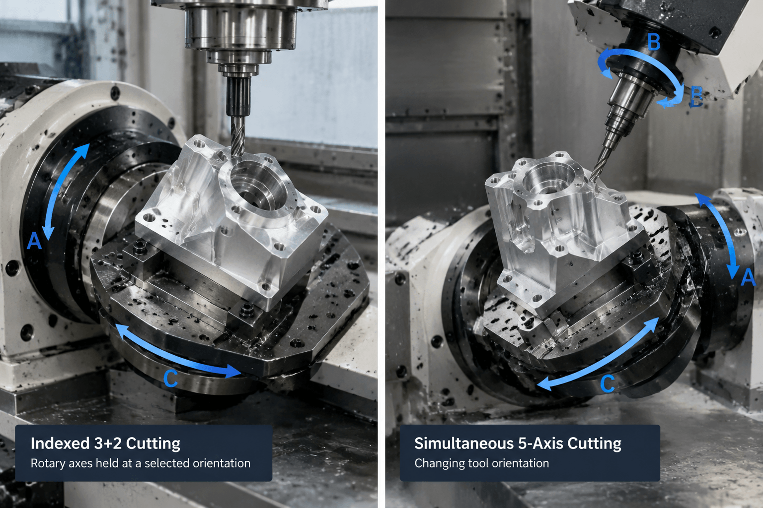
Not every machine described as five-axis moves all five axes together while cutting. Two operating methods must be distinguished.
Indexed 3+2 machining
The machine uses its two rotary axes to position the workpiece or tool at a selected angle. Those rotary axes are then held stationary while cutting proceeds with X, Y, and Z. The machine can index to another orientation for the next feature.
Simultaneous five-axis machining
The linear and rotary axes move in a coordinated path during cutting. The tool orientation can change continuously as it follows the programmed surface. This requires suitable machine kinematics, controls, post-processing, programming software, and collision management.
Same conceptual part, different motion
3+2: tilt to an angled face → lock orientation → mill the planar pocket.
Simultaneous: move along a contoured surface → continuously change tool position and orientation.
Machine descriptions may use “five-axis capable” without clearly stating whether simultaneous interpolation is included, enabled, or demonstrated. Verify the control functions, rotary limits, post-processor support, and an actual cutting demonstration. The demonstration should use the same operating mode being evaluated.
Industrial Mills, Desktop Machines, and CNC Routers
Machines carrying similar axis labels are not necessarily comparable. “Desktop” primarily describes scale, while “router” and “mill” suggest general construction or intended use but do not establish material capability on their own.
An industrial 5-axis CNC mill is normally evaluated through characteristics such as structural rigidity, spindle speed and torque behavior, bearing arrangement, axis-drive design, work envelope, rotary-axis capacity, toolholding, coolant management, chip evacuation, control functions, and provisions for measurement or automation. The relevant combination depends on the material, cutter size, operation, and required production cycle.
A 5-axis desktop CNC machine may be useful for education, prototypes, models, or light cutting when its specifications match the task. Its compact size does not reveal how it behaves under sustained cutting loads. Buyers should check allowable workpiece size and mass, spindle characteristics, frame construction, toolholding, duty cycle, and supported software.
A 5-axis CNC router may use a moving gantry and high-speed spindle suited to particular sheet, composite, plastic, wood, foam, or nonferrous-metal applications. That label does not mean every router can perform the same cuts as an industrial machining center. Material compatibility must be judged from the complete machine specification and a representative demonstration.
Searches for 5 axis mill price or 5 axis CNC price also need context. Cost can vary with machine size, rotary architecture, spindle system, control options, simultaneous machining functions, tool changer, probing, automation, software, installation, training, and included accessories. A low headline price may describe a different equipment category or exclude items needed for operation, so unsupported price bands are not useful for comparison.
What the Five-Axis Label Leaves Unanswered
Axis count primarily indicates potential directions of controlled motion. It can suggest improved access to multiple faces or complex surfaces, but it does not establish the dimensional result. Accuracy and surface finish also depend on machine condition and calibration, thermal behavior, rigidity, cutting forces, workholding, tool selection, tool runout, programming, material behavior, and measurement methods.
Tool access is equally part-specific. A machine may have the required nominal rotary axes but still be unable to reach a feature because the spindle housing contacts the workpiece, the fixture blocks the approach, or the rotary axis cannot travel to the necessary angle. A long tool may improve reach while reducing rigidity. A tall fixture can create clearance but move the workpiece farther from the rotary center and change the cutting conditions.
Likewise, five-axis machining does not guarantee completion in one setup. The part may need repositioning to machine its underside, expose a clamping area, remove a temporary holding feature, or reach geometry obstructed by the fixture. Whether one setup is practical must be assessed from the complete part and workholding plan.
Part-specific tolerance claims should be supported by demonstrated performance on relevant material and geometry, along with a suitable inspection method. A sample cut that proves movement is not automatically evidence for every tolerance, finish, workpiece size, or production quantity.
Try this with an actual machine: compare its axis diagram and a cutting demonstration with a representative part. Identify which two rotary axes are present, where they are located, and their travel limits, then trace each required tool approach. Check whether simultaneous interpolation is supported and demonstrated, and compare the demonstrated workpiece, tooling, fixture, material, and cutting mode with your intended application.