
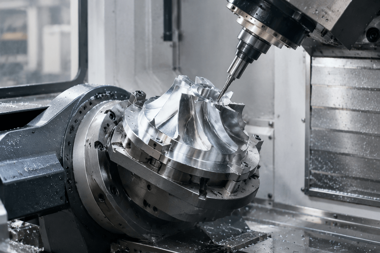
5-axis milling is a CNC machining process that uses three linear axes and two rotary axes to orient the cutting tool and/or workpiece, allowing the tool to approach a part from multiple directions. It is useful for complex surfaces, angled holes, deep features, and components that would otherwise require several setups.
In practical terms, 5-axis milling helps keep the tool correctly oriented to difficult geometry while reducing the need to reposition the workpiece. It can be used in simultaneous mode, where several axes move during cutting, or indexed mode, where the machine moves to a selected orientation and then cuts a feature from that fixed position.
The process is not automatically better or less expensive than simpler machining. The right choice depends on the part geometry, material, quantity, programming effort, workholding, tooling, inspection requirements, and the access available from other machining methods.
What 5-Axis Milling Makes Possible
A conventional 3-axis milling operation generally approaches the part from one fixed tool direction while the machine moves the tool along three linear axes. A 5-axis process adds two rotary movements, giving the tool or workpiece more orientation options. The exact mechanical arrangement varies by machine, but the practical result is greater access to angled and compound features.
In simultaneous 5-axis milling, multiple axes move together while the cutter follows a complex path. This is useful when the tool must continuously change angle across a compound surface, such as a contoured aerospace-style component or a moulded form. Maintaining a suitable tool angle can improve access and help avoid cutting with an unsuitable part of the cutter.
In indexed 5-axis milling, the machine rotates the part or tool to a new orientation, locks that orientation for the operation, and then performs a machining cycle. This approach is often suitable for a component with features on several faces, such as angled bores, side pockets, or cross-drilled holes. It is still a multi-axis process, but the cutting itself may occur in a series of stable orientations rather than through continuous rotary motion.
The main practical benefit is access. A part that would require repeated removal, repositioning, and re-zeroing on a simpler machine may be machined from fewer setups. Fewer setups can support better datum control and consistency, but they do not guarantee lower cost or shorter cycle time. Programming, simulation, fixture design, and inspection can become more demanding as the geometry becomes more complex.
From CAD Model to Inspected Component
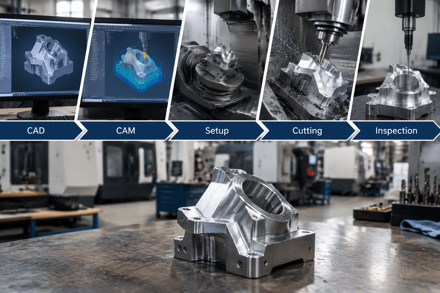
A 5-axis job is developed as a connected sequence of engineering, machining, and verification decisions. The general workflow is as follows:
- Review the CAD model and drawing. The programmer identifies the material, stock condition, critical dimensions, datums, surface requirements, holes, pockets, compound surfaces, and features that may be difficult to reach. A drawing remains important because the 3D model may not define every inspection or finishing requirement.
- Plan the machining approach. The team decides which features can be cut in 3-axis or indexed orientations and which areas benefit from continuous tool-axis control. This stage also considers stock allowance, access around the part, tool length, workholding, and the order of operations.
- Create CAM toolpaths. CAM programming converts the model and machining plan into tool movements. Strategies may include roughing, rest machining, contouring, swarf-style cutting, drilling from angled orientations, and finishing with a controlled tool axis. The correct strategy depends on the geometry and material rather than on the number of axes alone.
- Control tool orientation. The programmer defines how the cutter approaches the surface and how quickly its orientation changes. Tool-axis motion must account for holder clearance, local curvature, gouge avoidance, and the ability of the machine to follow the programmed movement smoothly.
- Simulate and check for collisions. A simulation should review the cutting tool, holder, spindle, fixture, stock, and machine movement where the available software supports that level of checking. This helps identify collisions, excessive tool tilting, unreachable features, gouging, and rotary-axis behavior before cutting begins.
- Set up the machine. The workpiece is secured against a suitable datum scheme, and the fixture is positioned to provide both rigidity and access. Work offsets, tool data, stock orientation, and probing or measurement routines are established according to the production plan.
- Rough, semi-finish, and finish the part. Material is removed in stages appropriate to the geometry and material. Cutting parameters are selected with regard to cutter diameter, engagement, tool length, material behavior, machine stability, chip evacuation, and heat generation. Finishing passes may use different tool orientations from roughing passes.
- Deburr within the defined process boundary. Edges may require deburring or another finishing operation, but these activities should be specified separately from the milling operation when they affect appearance, fit, or safety.
- Inspect critical features. Inspection confirms the dimensions, locations, angles, surfaces, and datum relationships that matter to the part function. The inspection method depends on the drawing, tolerances, geometry, and customer requirements.
Technical Choices That Control the Result
Five-axis capability does not compensate for weak process planning. The fixture, toolpath, cutter, and cutting conditions must work together.
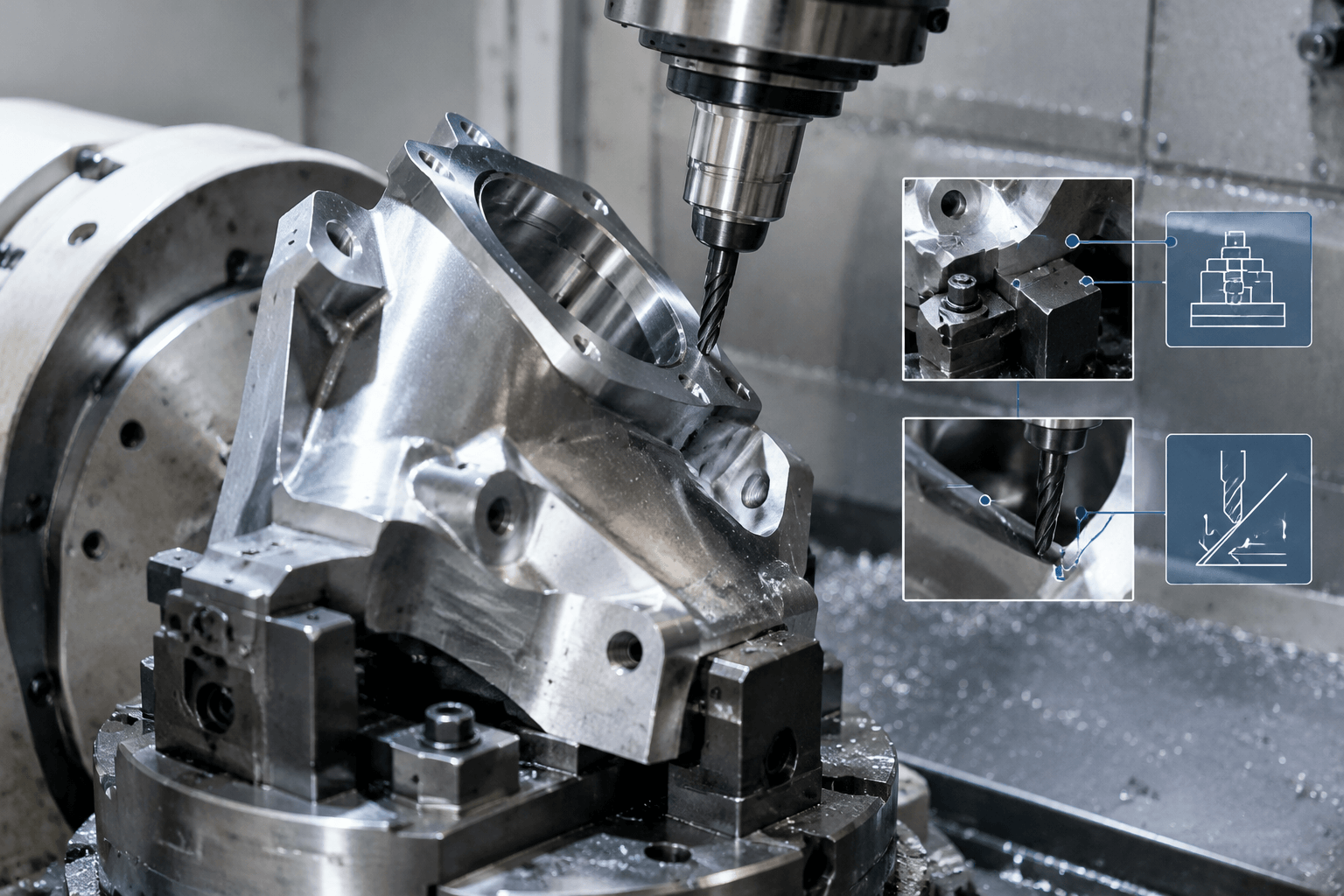
Workholding comes first. The fixture must hold the part rigidly while leaving enough clearance for the cutter, holder, spindle, and rotary movement. A fixture that blocks one face may defeat the access advantage of 5-axis machining. At the same time, an overly open fixture can allow vibration or movement. The workholding concept therefore balances access, support, datum repeatability, chip clearance, and safe clamping force.
Tool length affects stability. Long tools may be necessary to reach deep features, but they are generally more sensitive to deflection and vibration. Where the geometry permits, a shorter tool and suitable holder provide a more stable cutting condition. The programmer also needs to check that the holder does not contact an adjacent wall or surface as the tool tilts.
Tool orientation changes cutting behavior. A controlled tilt can improve access and help avoid cutting directly at an unfavorable point on a ball-nose cutter. However, rapid or excessive orientation changes may create poor surface transitions, difficult machine motion, or holder collisions. Orientation should follow the surface geometry and the selected cutter, not simply maximize the number of rotary movements.
Cutting parameters are material- and geometry-dependent. Spindle speed, feed rate, axial depth, radial engagement, step-over, coolant or air strategy, and toolpath direction must be selected for the alloy or material, cutter type, tool overhang, machine condition, and feature size. Deep pockets and enclosed features also require attention to chip evacuation and heat control. There is no universal parameter set that applies to every 5-axis job.
Process control point: Simulation and inspection address different risks. Simulation helps evaluate movement, access, gouging, and collision risks before machining. Inspection verifies whether the completed part meets the defined dimensional and geometric requirements.
Does This Part Benefit From 5-Axis Milling?
The following comparison connects common geometry problems with likely process choices. It is a starting point for process planning, not a universal rule.
| Part condition | Likely process fit | Reasoning |
|---|---|---|
| Flat faces, open pockets, and features reachable from one direction | 3-axis milling may be sufficient | A simpler setup and toolpath may provide the required access without rotary positioning. |
| Features arranged around a cylindrical or indexed form | 4-axis or indexed 5-axis milling may be suitable | The part may need rotary access, but continuous tool-axis movement may not be necessary. |
| Angled holes or side features on several faces | Indexed 5-axis milling may be useful | Multiple orientations can reduce repeated repositioning and improve access to the feature faces. |
| Compound surfaces requiring changing tool orientation | Simultaneous 5-axis milling may be appropriate | The cutter can follow the surface while maintaining a controlled angle. |
| Rotationally symmetric shafts, bores, or turned profiles | Turning may be the more natural process | Turning removes material through workpiece rotation and is conceptually different from milling. |
| Flat sheet, formed panels, brackets, or welded frames | Sheet metal fabrication, forming, or welding may be more appropriate | These processes create or join metal products rather than remove most of the material from a solid billet. |
| Parts requiring coating, plating, polishing, or joining | Finishing or assembly is needed in addition to machining | 5-axis milling does not replace surface treatment, welding, fastening, or final assembly. |
Information Needed for a Technical Review
An initial process review is more useful when the geometry and functional requirements are clear. The usual inputs include:
- A current 3D CAD model and 2D drawing where available.
- Material, stock condition, and planned quantity.
- Critical dimensions, tolerances, datums, hole locations, and angular requirements.
- Surface-finish or appearance requirements, with the relevant faces identified.
- Features that create access concerns, including angled bores, deep pockets, compound surfaces, and multiple machined faces.
- Inspection expectations, packaging constraints, and any downstream assembly interface.
These details help determine whether 5-axis milling is justified, whether indexed machining is enough, or whether another manufacturing method is more appropriate for the component. A technical review can focus on process fit, setup access, and the information needed to evaluate the manufacturing route.
Planning a component with difficult access? Share the 3D CAD model or drawing, material, planned quantity, critical features, tolerances, surface requirements, and any angled, deep, or multi-face features causing concern. A technical project review can then assess the likely setup approach, access constraints, and the information needed to evaluate a custom manufacturing route.
Frequently Asked Questions
What is the main difference between 4-axis and 5-axis milling?
Both add rotary movement to conventional linear milling, but 5-axis machining provides an additional degree of orientation control. In practical terms, 4-axis work may be well suited to indexed or cylindrical features, while 5-axis machining can provide more flexible access to multiple faces and compound surfaces. The useful distinction depends on the part geometry and required tool orientation.
How much does 5-axis milling cost, and what factors affect the price?
There is no universal price because cost depends on material, part size and geometry, quantity, programming complexity, workholding, tooling, cycle time, setups, finishing, and inspection requirements. A part that benefits from fewer setups may still require substantial CAM programming or specialized tooling. A drawing and model are needed before a meaningful estimate can be considered.
What type of CNC machine is used for 5-axis milling?
A CNC machining center with three linear movements and two coordinated rotary movements is used for 5-axis milling. The rotary movements may be arranged through a tilting table, a swiveling spindle, or a combination, depending on the machine design. The important production questions are the required access, workholding arrangement, tool clearance, and programmed motion rather than the configuration name alone.
Is 5-axis milling always better than 3-axis milling?
No. 3-axis milling may be more suitable for accessible faces, simple pockets, and parts that can be machined efficiently from a stable setup. 5-axis milling becomes more useful when the part has angled or multi-face features, compound surfaces, or access problems that make repeated setups undesirable. Process selection should be based on the complete geometry and inspection requirements.