
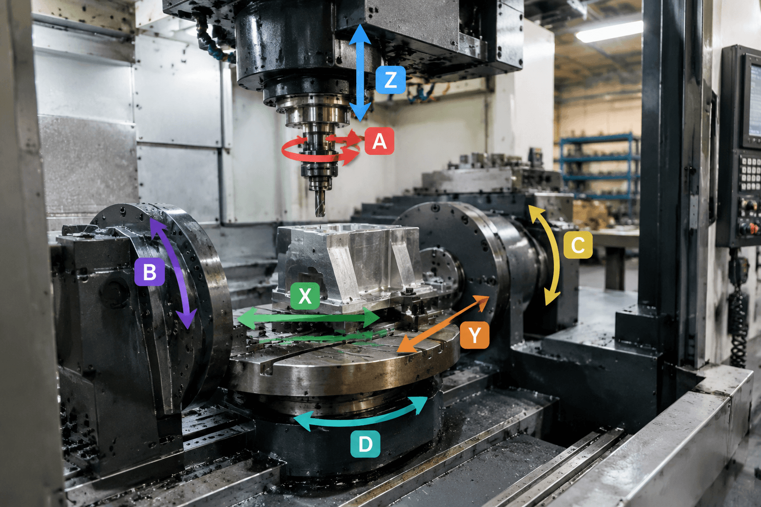
A 6-axis CNC machine combines three linear axes with three rotary axes, allowing the tool or workpiece to change position and orientation in more ways than a conventional 3-axis or many 5-axis configurations. However, “6-axis” does not necessarily mean that all six axes move simultaneously while cutting; the machine architecture, control, and machining strategy must be verified.
Quick answer: The sixth axis may provide an additional rotary movement, often associated with tool or workpiece roll around the cutting direction. Its practical value depends on whether it participates in continuous interpolation, only indexes the part between operations, or is configured in another way.
This distinction matters when evaluating a machine, machining supplier, or an online search for a “6-axis CNC machine.” A higher axis count can help with access to compound geometry, but it is not automatically a guarantee of better accuracy, surface finish, shorter cycle time, fewer setups, or lower cost.
What Moves on a 6-Axis CNC?
A basic 3-axis CNC mill moves the cutting tool or workpiece along three linear directions. These are commonly called X, Y, and Z. Depending on the machine layout, they may represent left-to-right, front-to-back, and vertical travel, although the physical direction associated with each label depends on the machine coordinate system.
Rotary axes add angular movement. A common naming convention describes A as rotation around X, B as rotation around Y, and C as rotation around Z. In a nominal six-axis arrangement, the machine may therefore combine X, Y, and Z linear motion with A, B, and C rotary motion. This is a useful way to understand the motion categories, but it is not a universal description of every machine.
The rotary axes can be installed in different ways. They may be carried by the spindle head, built into a rotary table, or divided between the tool side and workholding side. These arrangements affect the work envelope, payload, rigidity, collision behavior, and the way the control calculates tool orientation. The same axis label can therefore represent different physical movements on different machine architectures.
The third rotary capability may allow an additional orientation change, potentially including roll around the cutting direction. That can be useful when the tool needs to maintain a preferred orientation while following a changing surface. It is not an unconditional capability: available tool roll and its effect depend on the machine structure, tooling, control system, and programmed tool path.
Simultaneous Six-Axis Machining Versus 5+1
The most important question is not simply how many axes a machine has. It is whether the additional axis participates in the cutting motion at the same time as the other axes.
Simultaneous six-axis interpolation means that the control coordinates six axes together during at least part of the cutting operation. Linear and rotary positions can change continuously as the tool follows the programmed path. This may help with complex, twisting, or continuously changing surfaces, provided the machine has suitable kinematics, programming, post-processing, and collision verification.
5+1 machining generally means that five axes are interpolated during cutting while the additional axis is used to index or reposition the tool or workpiece. After the extra axis reaches a new position, the cutting operation may proceed using the other five axes. A machine can therefore have six physical axes without offering true simultaneous six-axis cutting for the operation being considered.
| Machining approach | Motion behavior | Geometry and access relevance | What to verify |
|---|---|---|---|
| 5-axis | Three linear axes and two rotary axes are coordinated during cutting. | Often suitable for multi-sided parts, angled features, and many compound surfaces. | Which two rotary axes are available, their travel, and how they affect access and collisions. |
| 5+1 | Five axes interpolate; the additional axis indexes or repositions between cutting operations. | Useful when several fixed orientations provide adequate access without continuous six-axis motion. | Whether the extra axis is available only for positioning and how many indexed orientations the process needs. |
| Simultaneous 6-axis | Six axes can be coordinated continuously during the relevant cutting operation. | May help with continuously changing tool orientation, compound curvature, or difficult access conditions. | Actual interpolation capability, machine kinematics, post-processor support, and collision simulation. |
When discussing a specific part, ask the machining provider to identify which axes move during the actual operation. A general machine brochure or search result may use “6-axis” as a physical axis count, while the process may still be programmed as 5+1 or as a sequence of indexed operations.
When Does Six-Axis Motion Help Part Geometry?
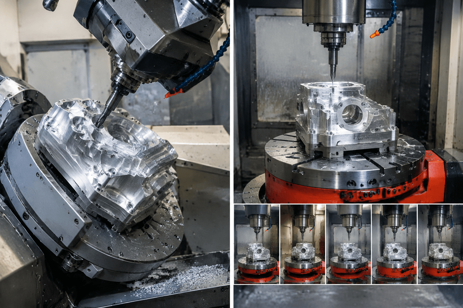
Axis selection should begin with the part’s surfaces, features, and required access rather than with the largest available axis number. Many components can be machined effectively with 3-axis, 4-axis, 5-axis, or indexed methods. Simultaneous six-axis motion becomes more relevant when the cutting tool must change orientation continuously in more than two rotational directions as it follows the geometry.
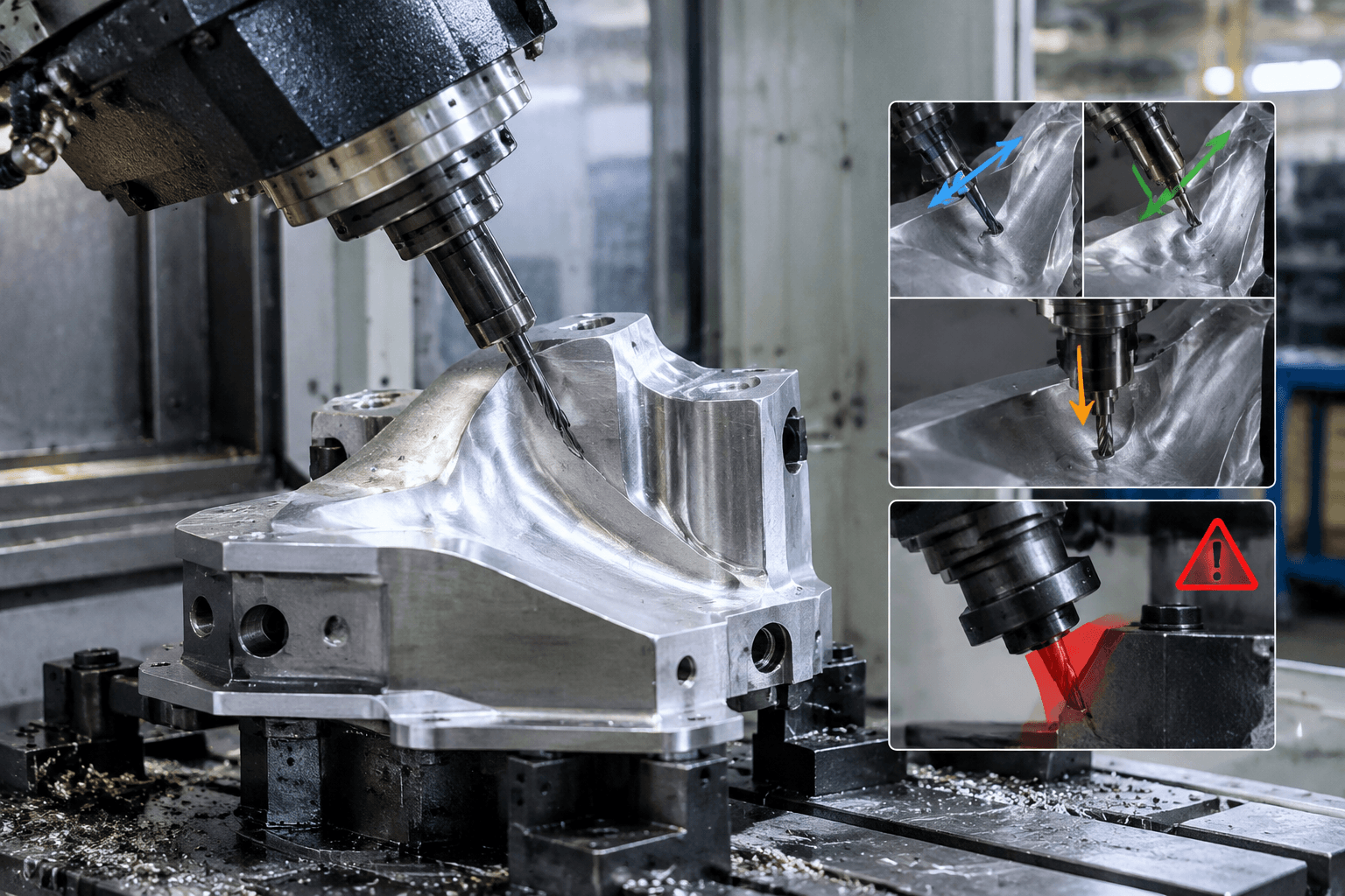
Consider a hypothetical compound surface that twists while its normal direction changes along several axes. A 5-axis process may provide adequate access in some regions, but it may also require a compromise in tool orientation, additional indexed positions, or a different setup strategy. A third rotary movement could provide another way to manage tool roll or approach direction. Whether that produces a practical benefit depends on the machine’s kinematics and the tool path, not on the axis count alone.
Potentially relevant geometry categories include deeply contoured surfaces, twisted forms, and components with several changing approach directions. Turbine-blade-like or organic implant-like shapes can be used as illustrative geometry categories, but they do not automatically require six-axis machining. The actual need depends on curvature, tool access, material, feature size, workholding, and the required manufacturing process.
Access is only one consideration. Extra rotary motion can also introduce more possible orientations and collision conditions. The programmer may need machine-specific post-processing, kinematic checks, and collision simulation. The operator and process engineer must understand how the selected tool, holder, spindle head, workpiece, and fixtures interact throughout the path.
For a part with multiple flat faces and fixed angled features, 5+1 may be a sensible approach. It can reposition the workpiece or tool between operations without requiring continuous six-axis interpolation. For a part whose surface direction changes gradually and unpredictably, simultaneous motion may be more relevant. A technical review of the model or drawing is needed to distinguish these cases.
What the Axis Count Does Not Tell You
The label “6-axis CNC” does not by itself define the machine’s useful capability. Before deciding that a process requires six-axis machining, check the architecture and operating limits that affect the actual part.
- Axis arrangement: Determine whether the rotary axes are on the head, table, or split between them. This affects reach, workholding, and collision behavior.
- Work envelope and payload: The machine must accommodate the part, fixture, tool holder, and required rotary movement without exceeding its usable range.
- Rigidity and spindle configuration: These influence how the machine handles the material, tool engagement, and cutting forces. They cannot be inferred from axis count.
- Control and interpolation: Confirm whether all relevant axes can be coordinated during cutting, rather than assuming that six physical axes provide six-axis interpolation.
- Programming and verification: Simultaneous rotary motion may require an appropriate post-processor and reliable collision checking. These are implementation requirements, not automatic consequences of the machine label.
- Achievable part result: Tolerance and surface finish depend on the complete process, including material, tooling, setup, programming, machine condition, inspection, and specification. Axis count alone cannot establish them.
Searches for 7-axis CNC and 9-axis CNC need the same caution. These labels can describe different combinations of linear and rotary axes, additional tool or workpiece movements, or a combined machine that performs more than one machining function. A 7-axis machine in one architecture may not be directly comparable with a 7-axis machine in another. The same applies to 9-axis terminology, particularly when turning and milling functions are combined.
For this reason, a buyer should request an axis diagram, identify which axes are interpolated during the target operation, and confirm the relevant work envelope and control behavior. Machine purchase prices and machines advertised for sale are separate commercial questions; configuration, automation, tooling, and application requirements can all affect price, so axis count is not a reliable price indicator.
When the geometry is still being evaluated, share the part model or drawing with a qualified machining provider and ask whether the critical surfaces require simultaneous six-axis motion, 5-axis cutting, or indexed 5+1 positioning.
Frequently Asked Questions
What is the difference between 5-axis and 6-axis CNC?
A 5-axis machine typically combines three linear axes with two rotary axes. A six-axis arrangement adds another rotary movement, but that axis may either interpolate continuously during cutting or only reposition the tool or workpiece between operations.
How can you tell whether a 6-axis machine interpolates all six axes during cutting?
Ask for the machine’s axis configuration and confirmation of simultaneous interpolation for the specific operation. Also verify the control, post-processor, tool-path simulation, and whether the additional axis is used for cutting or only indexed positioning.
Is there a 7-axis CNC, and what does the extra axis usually describe?
Yes, the term is used for machines with seven coordinated or available motion axes. The extra movement may belong to the tool head, workholding system, a secondary spindle, or another machine function, so the label is not a universal measure of cutting capability.
Is there a 9-axis CNC machine, and is its axis count comparable across machine types?
Yes, but 9-axis descriptions can refer to different combined milling, turning, tool, and workpiece arrangements. Compare the actual axis diagram, interpolation behavior, work envelope, and intended operation instead of treating the number as a standard capability rating.