
Resistance spot welding is one of the most common joining methods for sheet metal assemblies, but its reliability depends heavily on decisions made before production starts.
For buyers and engineers, spot weld quality is not only a welding issue. It is also a design issue, a process-control issue, and a quality-verification issue. Weak spacing rules, poor overlap, unstable parameters, or inconsistent material conditions can all lead to defects that appear much later in production or field use.
This guide explains the practical rules behind sheet metal spot welding, when it is the right joining method, why some materials are harder to weld, how common defects develop, and what buyers should confirm before approving a welded assembly supplier.
Why Spot Welding Problems Usually Start Before Welding
In sheet metal assemblies, many spot weld failures begin with the part design rather than the welding machine itself. If spacing, overlap, or accessibility are wrong, even a well-set process can produce weak or inconsistent joints.
Core Design Rules for Spot Welding
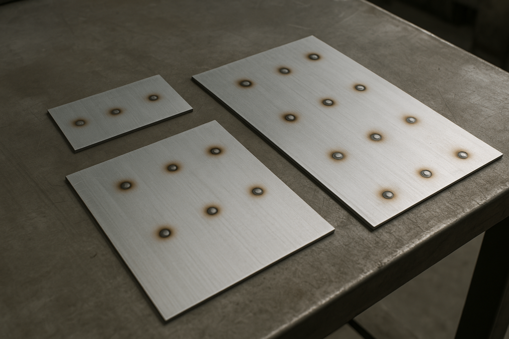
Weld Spacing (Pitch)
If spot welds are placed too close to each other, current can be diverted through an existing weld. This current shunting reduces heat at the intended weld interface and can produce a smaller or weaker nugget.
Weld Edge Distance
Welds placed too close to a free edge are more likely to cause blowout, expulsion, or edge distortion because the surrounding material cannot support stable heat concentration.
Flange Overlap Width
The overlap must be wide enough to support both the weld nugget and electrode positioning. If the flange is too narrow, repeatability drops and the joint becomes harder to control.
Tool Accessibility
A weld location that looks acceptable on a drawing may still be impractical if the electrodes cannot approach the joint cleanly. Accessibility should be checked during design, not after fixtures and tooling are already in place.
How Resistance Spot Welding Actually Works
Resistance spot welding creates a joint by passing electrical current through overlapped sheet metal while force is applied by electrodes. Heat is generated mainly at the faying interface, where electrical resistance is highest, and this heat forms the weld nugget.
Why Current, Force, and Time Matter
In practical production terms, the process is controlled by three main variables:
electrode force;
welding current;
weld time.
These variables work together. Too little heat produces a weak or cold weld. Too much heat can cause expulsion or excessive indentation. That is why spot welding is usually managed as a process window rather than by one number alone.
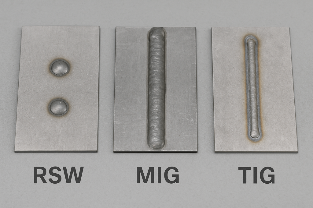
When Spot Welding Fits Better Than MIG or TIG
Spot welding is usually strongest where the assembly involves overlapped sheet metal, short cycle times, and high repeatability requirements.
RSW is often best for high-volume sheet assemblies;
MIG is more flexible for longer seams and general fabrication;
TIG is usually chosen where precision appearance or more delicate manual control is required.
For buyers, the most important question is not which process is “better” in general, but which process fits the joint design, production volume, and appearance requirements with the lowest long-run risk.
Why Special Materials Change the Equation
Spot welding mild steel is relatively straightforward compared with aluminum, galvanized steel, or advanced high-strength steel. These materials introduce additional process-control challenges that buyers should understand before approving a supplier.
Aluminum
Aluminum conducts heat and electricity very efficiently, which means it often requires higher current and shorter welding cycles. Its oxide layer also makes stable welding more difficult.
Galvanized Steel
The zinc layer can change heat behavior, increase spatter risk, and accelerate electrode wear. Parameter control becomes more sensitive than with bare steel.
High-Strength Steel (AHSS)
AHSS may develop brittle microstructures in the heat-affected zone if welding parameters are not managed properly. That makes process discipline especially important.
Common Spot Weld Defects and What Causes Them
Common spot weld defects usually reflect imbalance in force, current, time, fit-up, surface condition, or electrode condition.
| Defect | Common Cause | Typical Response |
| Expulsion / spatter | excessive heat or unstable fit-up | review current, force, and part fit |
| Cold weld | insufficient heat input | review current, time, and electrode condition |
| Burn-through | too much localized heat | lower heat input and review hold conditions |
| Excessive indentation | too much force or poor tip condition | review force and electrode geometry |
How Buyers Verify Spot Weld Quality
For buyers, spot weld quality should be verified through both process validation and production control rather than visual appearance alone.
Process Validation
Peel tests, destructive checks, or nugget confirmation are often used during setup or qualification to confirm that the weld forms correctly.
In-Line Monitoring
During production, manufacturers may use current monitoring, force control, or non-destructive inspection methods to track consistency.
Adaptive Quality Control
More advanced systems can monitor variation and react to drift in real time, but buyers should confirm what level of monitoring actually exists in the quoted production process.
What Buyers Should Confirm in RFQ
Before approving a spot-welded assembly, buyers should try to confirm:
material grade and thickness combination;
weld quantity and location logic;
cosmetic versus structural importance of the weld area;
inspection or validation method;
electrode accessibility and fixture assumptions;
whether special materials require special parameter control.
FAQ
What thickness range is usually suitable for spot welding?
Spot welding is most commonly used on thin to medium sheet combinations, but the suitable range still depends on material type, access, and required joint strength.
Can aluminum be spot welded the same way as mild steel?
Not usually. Aluminum typically requires different parameter control because of its conductivity and oxide layer behavior.
Is spot welding stronger than MIG or TIG?
That depends on the joint type and loading direction. Spot welding is highly effective for overlapped sheet joints, while MIG or TIG may be more suitable for seam welding or different joint geometries.
Do all welds need to be individually specified?
Not always, but critical weld locations, quantity logic, and acceptance standards should be clearly defined when they affect structural or cosmetic performance.
Conclusion
Spot welding quality depends on much more than the welding machine. Joint design, material behavior, parameter stability, accessibility, and quality verification all shape whether the assembly performs consistently in production.
For buyers, the most effective way to reduce risk is to evaluate spot welding as a complete system: design rules first, process window second, material behavior third, and inspection discipline throughout.
