
Introduction: A 10,000 Horsepower Engineering Decision
Choosing aluminum connecting rods is not simply a weight-saving decision. In high-output racing engines, it is an engineering choice made to manage extreme combustion forces.
That is why Top Fuel dragsters and Pro Mod engines often use aluminum rods, even though many buyers instinctively associate steel with strength and aluminum with lightness. The reality is more nuanced. Steel is rigid and durable; aluminum is lighter, more elastic, and better at absorbing shock in certain high-horsepower applications.
This guide is written for professional engine builders, wholesale performance-parts buyers, and sourcing teams evaluating custom connecting rods. It explains where aluminum rods make sense, where they do not, and what buyers should check before placing a batch or custom order.
The goal is not to repeat marketing claims. It is to connect material behavior, fatigue life, manufacturing method, installation practice, and procurement risk into one practical decision framework.
The Fundamental Question: Why Choose Aluminum Over Steel?
The aluminum vs. steel connecting rod debate is really about force management. In a high-output engine, the rod must survive repeated combustion pressure, acceleration loads, vibration, and heat. The strongest-looking material on paper is not always the best choice in the engine.
The Role of Steel: The OEM Standard
Forged steel rods remain the standard for production vehicles for good reason. They offer strength, rigidity, and long service life under predictable operating loads. For daily-use engines and conventional OEM applications, that rigidity is an advantage because it supports stable power transfer.
In extreme horsepower applications, however, the same rigidity can become a weakness. When boost or nitrous creates sudden pressure spikes, a rigid steel rod transfers much of that shock directly into the bearings and crankshaft. In the wrong setup, this can contribute to severe component failure.
The Aluminum Advantage: More Than Just Weight Savings
Aluminum rods do reduce reciprocating mass. That can help the engine accelerate faster and improve throttle response. But for serious racing applications, weight is only part of the story.
The more important advantage is elasticity.
The “Shock Absorber” Secret
Aluminum has a lower modulus of elasticity than steel. In plain terms, it can flex slightly under extreme load and then return to shape when used within its proper design limits.
That small amount of “give” matters. In a power-adder engine, an aluminum rod can help cushion the violent force of combustion. Instead of transmitting the shock as sharply as a rigid steel rod, it spreads the load over a slightly longer moment.
This is why aluminum rods are sometimes described as shock absorbers inside the engine. They help protect the crankshaft and rod bearings under extreme cylinder pressure, which is exactly where high-output racing engines place their greatest demands.
Durability Dilemma: How Long Do Aluminum Connecting Rods Last?
One of the most common questions buyers ask is: how long do aluminum connecting rods last? The answer is not “one run” and it is not “forever.” Their lifespan depends on the engine combination, power level, operating cycle, and inspection discipline.
For procurement managers, this matters because aluminum rod life affects customer guidance, inventory planning, and after-sales expectations.
Debunking the “Single-Use” Myth
The “single-use” idea is one of the most persistent aluminum rod myths. In reality, usable life depends on load severity.
- Top Fuel / Pro Mod: Rods are treated as scheduled consumables and may be replaced after only a handful of runs.
- Bracket Racing: In milder combinations, aluminum rods can last for hundreds of passes.
- High-Performance Street / Strip: Many builders recommend proactive replacement after 10,000 to 15,000 miles.
So the question is not whether aluminum rods last. They do. The real question is whether the expected service interval matches the engine’s power level and use case.
The Science of Fatigue Life
The key difference between aluminum and steel is fatigue behavior. Steel has an endurance limit. Below a certain stress level, it can theoretically last indefinitely.
Aluminum alloys do not have that same endurance limit. Their fatigue curve continues downward, which means every stress cycle consumes a small portion of the part’s finite fatigue life.
This does not make aluminum unreliable. It simply means the part must be engineered, inspected, and replaced according to its application. Finite Element Analysis (FEA) helps predict stress concentration zones and estimate cycles to failure, making aluminum rod life manageable rather than mysterious.
For wholesale buyers, this is an important communication point. Aluminum rods should be sold with clear application guidance, not vague promises of universal durability.
Manufacturing Process Duel: Forged vs. Billet?
For wholesale buyers, the forged vs. billet debate affects more than technical preference. It influences tooling cost, batch consistency, lead time, customization flexibility, and final pricing.
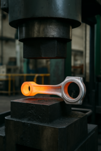
Forging: Strength in Alignment
Forging uses dies and high pressure to shape heated aluminum. This process aligns the internal grain flow with the part’s geometry, improving fatigue resistance and impact strength.
The trade-off is tooling cost. Forging makes the most sense when the part is standardized and production volume is high enough to justify the die investment. For recurring orders, it can provide strong batch-to-batch consistency at a competitive unit cost.
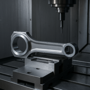
Billet: The Art of Precision and Customization
Billet aluminum rods are machined from solid aluminum stock using CNC equipment. This subtractive method offers excellent design flexibility, making it suitable for custom billet aluminum rods, prototype development, and small-batch production.
The limitation is grain flow. Billet material has a uniform structure, but the grain is not shaped around the final rod geometry in the same way forging can achieve. Even so, for custom applications, precise CNC machining and design control often matter more than theoretical grain alignment.
The Verdict for Procurement
Forging offers a strength advantage in grain alignment, but process quality still matters. A billet rod machined from premium certified aluminum can outperform a forged rod made from weaker material or poor tooling.
For procurement teams, the decision should be based on volume, application, material certification, dimensional requirements, and customization needs. Forged rods fit standardized high-volume programs. Billet rods fit custom, lower-volume, or specialized racing applications.
Structural Design Showdown: I-Beam vs. H-Beam?
The I-beam vs. H-beam connecting rod discussion is really a question of load direction and geometry. The rod shape should match how the engine loads the part, not just what looks stronger on a product page.
I-Beam: The King of Compression
The I-beam shape concentrates material along the outer edges, helping resist bending and buckling under high compression loads.
For boosted engine rods and high-strength aluminum rods used in turbo applications, this geometry can be especially effective. It gives the rod a strong compression path while keeping weight under control.
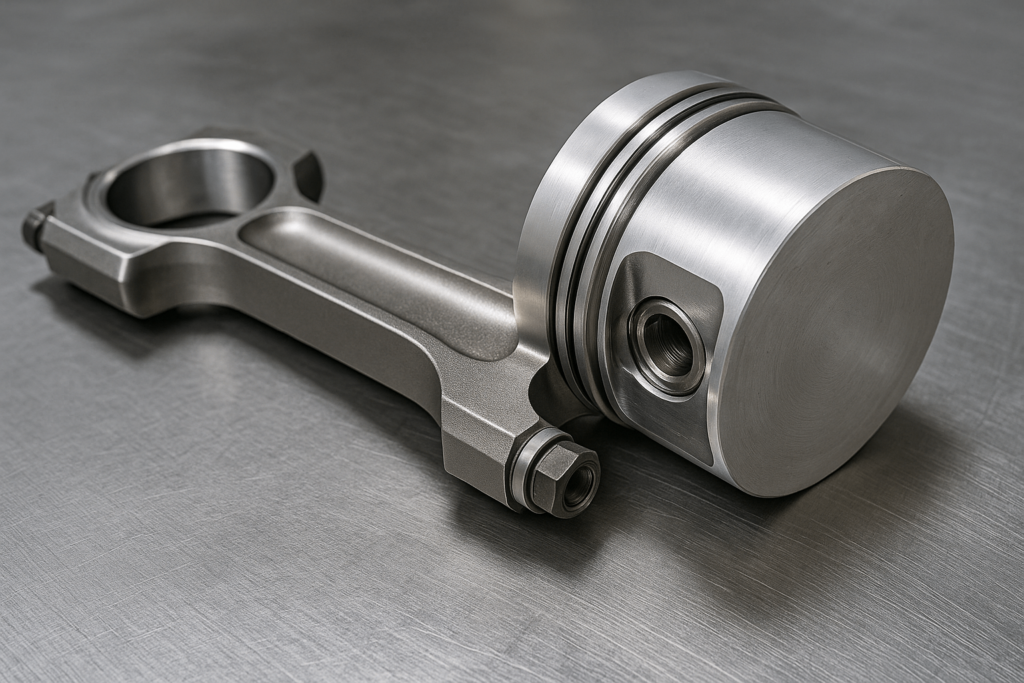
Installation & Customization Masterclass: How to Install Aluminum Connecting Rods with Proper Clearances
Aluminum rods require careful installation. Even a well-made rod can fail if clearances, bolt preload, or thermal expansion are ignored. For wholesale partners, clear installation guidance reduces misuse, complaints, and avoidable returns.
Critical Clearances You Can’t Ignore
- Piston-to-Head Clearance: Aluminum’s higher thermal expansion and dynamic stretch require more clearance. A typical piston-to-head clearance for aluminum rods is .060 to .080 inches, compared with .040 inches for steel.
- Bearing and Side Clearances: A minimum rod bearing clearance of .0025 inches is required to account for thermal expansion of the big-end bore.
These values should be treated as application-sensitive guidelines. Final clearances should always match the engine builder’s setup and manufacturer instructions.
Torque vs. Stretch: The Professional’s Method
For professional assembly, bolt stretch is more reliable than torque alone. Torque can be affected by lubricant, thread condition, and friction. Measuring physical bolt elongation gives a more direct reading of preload.
Correct preload helps keep the big-end bore round under load, making this a critical quality-control step during installation.
| Bolt Type | Recommended Stretch | Torque (with 50W oil) |
| 3/8” ARP 2000 | .0058” – .0064” | 65 ft-lbs |
| 3/8” L19 | .0065” – .0070” | 75 ft-lbs |
| 7/16” ARP 2000 | .0055” – .0060” | 80 ft-lbs |
| 7/16” L19 | .0060” – .0068” | 90 ft-lbs |
Data from R&R Racing Products installation guide.
Working with a Manufacturer: The YISHANG Process
Custom connecting rods should not be ordered from dimensions alone. The manufacturer needs to understand the intended engine type, power level, RPM range, service interval, and installation requirements.
YISHANG works with partners to define connecting rod dimensions and production details around the actual application. This kind of collaboration helps buyers avoid treating a high-stress engine component like a generic catalog item.
Conclusion: It’s Not Just a Part, It’s an Engineering Decision
Selecting aluminum connecting rods is not just a material choice. It is an engineering decision based on power level, shock loading, fatigue life, rod geometry, manufacturing process, and installation discipline.
Aluminum rods are not the best choice for every engine. But in high-stress racing applications, their ability to absorb shock can protect other critical components and help unlock reliable horsepower.
For professional builders and wholesale partners, the key is to match the rod to the application and to work with a manufacturer that understands both production quality and real engine behavior. YISHANG supports custom aluminum component projects with engineering review, machining capability, and batch-focused production control.
Frequently Asked Questions (FAQ)
Q: Can I use aluminum connecting rods in a daily driver street car?
It is generally not recommended. Steel rods offer the fatigue life needed for high-mileage use. Aluminum rods are better suited to racing and limited-use performance engines.
Q: Are aluminum rods stronger than steel rods?
In raw material strength, no. Their advantage is shock absorption. In high-horsepower engines, that elasticity can help them survive conditions where a rigid steel rod may transfer damaging loads to other components.
Q: How much lighter are aluminum connecting rods?
They can be around 100–150 grams lighter than comparable steel rods. This reduces rotating assembly mass and helps the engine accelerate and rev more quickly.
Q: Do aluminum connecting rods stretch?
Yes. All connecting rods stretch under load. Modern aluminum alloys reduce permanent stretch, but aluminum rods still require more initial piston-to-head clearance, typically .060″–.080″, to account for thermal expansion and dynamic stretch at high RPM.
