
In 30 seconds for buyers: good sheet metal design is not about perfect drawings. It is about reducing production risk. Designs that respect forming behavior, realistic tolerances, and volume repeatability lead to stable pricing, predictable lead times, and reliable reorders.
Overseas wholesale buyers don’t search for sheet metal design because they want theory. They search because they want fewer surprises: stable unit costs, predictable lead times, consistent batches, and parts that assemble without hand-fitting.
A drawing can look “correct” in CAD and still create headaches in real production. The difference is not style. It is how the design behaves during cutting, bending, welding, finishing, and repeat builds.
This article approaches metal fabrication design from a manufacturing-and-sourcing perspective. It is written for buyers and technical teams who need design decisions that hold up under volume, inspection, and reorders.
Why Sheet Metal Parts Fail After the Drawing Looks “Correct”
In day-to-day fabrication, most failures do not start with poor workmanship. They start with assumptions embedded in the drawing. Those assumptions are only tested when the part reaches a press brake, a fixture, and an assembly line.
A CAD model captures an ideal state. Flatness is assumed. Edges are perfectly straight. Dimensions look absolute. In the real world, sheet metal fabrication is controlled deformation, and geometry can shift—especially after bending cycles, fixture clamping, and heat input from welding or finishing.
For wholesale procurement, these technical effects translate directly into commercial risk. Designs that require constant adjustment drive cost creep. Unrealistic tolerances increase scrap and inspection time. Designs that only work once make repeat orders unstable.
What wholesale buyers are really evaluating
When buyers read technical content from suppliers, they are not looking for marketing language. They are checking for practical competence.
They want to know whether a supplier understands why parts crack, why holes drift after bending, why angles vary between batches, and why fixtures matter. Most importantly, they want to see whether the supplier thinks in terms of repeatability under normal shop conditions.
That is why strong sheet metal design content focuses on cause and effect. Explaining how design choices influence yield, inspection effort, and batch consistency speaks directly to procurement reality.
A simple risk lens buyers use
Most sourcing decisions pass through three internal questions.
Does the design stay consistent across batches.
Can it assemble without rework.
Will unit cost remain stable as volume increases.
Every section below ties back to these three concerns.
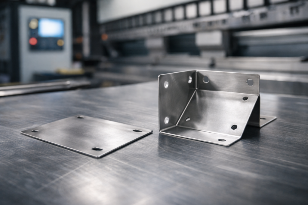
What Actually Changes When a Flat Sheet Becomes a Formed Part
A flat pattern is relatively predictable. Laser cutting or punching places features accurately, and the part carries little internal stress. Once bending begins, the mechanical state changes.
Bending changes the part by forcing the outer fibers into tension and the inner fibers into compression. Once the tool opens, elastic recovery—springback—nudges the final angle away from the programmed value. Meanwhile, the neutral axis location shifts with thickness, grade, tooling geometry, and the chosen forming method.
That is why flat pattern development relies on bend allowance, bend deduction, and the K-factor. Even with correct calculations, variation still exists. Material batches differ. Grain direction varies. Tooling wears. Setup conditions change.
Why this matters to sourcing and reorders
Variation itself is not the problem. Designs fail when they are not tolerant of normal variation.
If a design requires angles to land within an extremely narrow window, inspection burden rises and yield drops. If critical holes sit too close to bends, small forming variation becomes an assembly failure.
For buyers planning repeat orders, the safest designs are those that behave consistently across normal process changes. That means designing around process capability rather than ideal geometry.
Common post-forming changes buyers should expect
Even well-made parts show predictable shifts after forming. Hole positions may move slightly relative to bend lines. Flatness can change after multiple bends. Edges near tight bends may pull inward.
Good sheet metal design anticipates these effects and uses geometry, feature placement, and tolerance strategy to keep functional outcomes stable.
The Hidden Trade-Off Between Strength, Cost, and Manufacturability
Buyers often hear an internal request: make it thicker to be safe. Sometimes that is justified. Often it introduces new risk.
Thicker material increases strength, but it also raises bending force, accelerates tool wear, and increases unit cost. It can reduce manufacturability by limiting achievable bend radii and increasing cracking risk, especially in stainless steel and aluminum alloys.
In practical metal fabrication design, stiffness is frequently achieved through geometry rather than mass. Flanges, returns, hems, and ribs add strength with less material and lower forming force.
Why geometry usually wins in high-volume sourcing
Geometry-based stiffness improves sourcing outcomes by reducing material usage and forming load. Lower forming load generally leads to more stable angles and better repeatability.
For procurement teams, this translates into stable pricing and consistent lead times. Parts that require less force and fewer corrective steps tend to run faster and with fewer quality escalations.
Overdesign often appears as unnecessary thickness, overly tight tolerances, or complex features that add operations. None of these are free.
They increase cycle time, inspection effort, and scrap sensitivity. The most robust designs are rarely the most conservative on paper. They are the most stable in production.
Bending Problems Usually Start Before the First Bend
Bending is often treated as a chart-driven process. Minimum bend radius tables and K-factor charts are useful, but they are frequently applied without sufficient context.
Actual bend results depend on forming method, tooling selection, material batch behavior, and bend orientation relative to grain.
Bend radius is not just a number
A bend radius that meets published minimums can still crack if the grain direction is unfavorable, the bend line is too close to a cut feature, or tooling concentrates stress.
Bend-radius failures are expensive in sourcing because they tend to surface late in the cycle. Flat patterns cut cleanly. Pre-bend parts look acceptable. The first real warning often appears during forming or handling—when cracking shows up and a batch suddenly becomes nonconforming.
As a general reference, many manufacturers aim for an inside bend radius at least equal to material thickness for ductile steels, with larger radii preferred for less ductile alloys. Designs that push below this range often require tighter control and higher risk.
K-factor: useful, but not universal
The K-factor is often treated as a constant. In reality, it varies with forming method and tooling.
Experienced manufacturers validate flat patterns with production data and adjust K-factor inputs for repeatability. For buyers, this capability directly affects dimensional consistency and tooling stability on reorders.
Why consistent bend orientation matters
Variation rises when bend orientation is inconsistent. Bends formed parallel to grain and those formed across grain can spring back differently, even when the nominal tooling and settings are the same.
In volume programs, these differences compound into fit issues and higher inspection burden. Production-ready sheet metal design aims for consistent forming behavior across all bends.
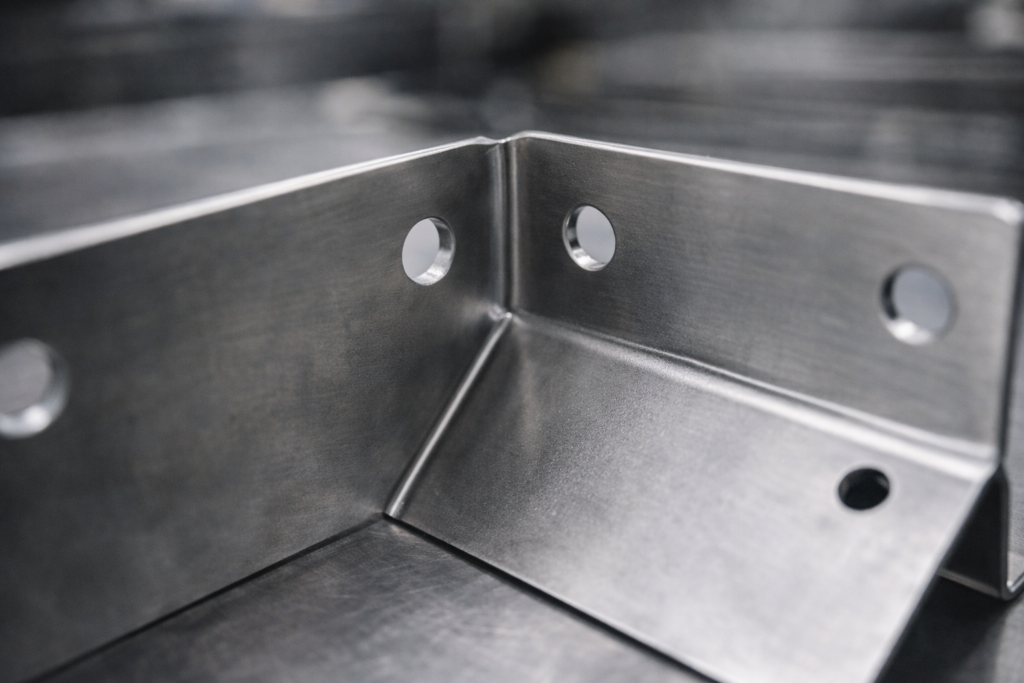
Why Holes, Cutouts, and Edges Behave Differently After Forming
In flat layouts, holes and cutouts appear as simple two-dimensional features. After forming, they become part of a stressed structure.
Holes near bends experience uneven stress as material stretches and compresses. The result can be slight positional shift or loss of roundness. These changes may be small, but in assemblies they can be decisive.
Hole-to-bend distance as a sourcing risk
From the buyer’s perspective, the key question is whether the hole will still function after bending across batches.
As a practical guideline, many fabricators recommend placing holes at least two material thicknesses away from bend lines. Designs that push closer often require secondary operations or relaxed mating clearances, increasing cost.
Cutouts and stress concentration
Sharp internal corners concentrate stress. They may survive prototyping but become cracking or fatigue initiation points in production.
Adding generous corner radii and appropriate bend relief is not over-engineering. It is a proven way to stabilize yield and extend service life.
Edge behavior and dimensional stability
Edges near bends can warp or pull inward, affecting overall dimensions and appearance.
A robust metal fabrication design places critical edges away from high-stress forming zones or uses geometry to control deformation.
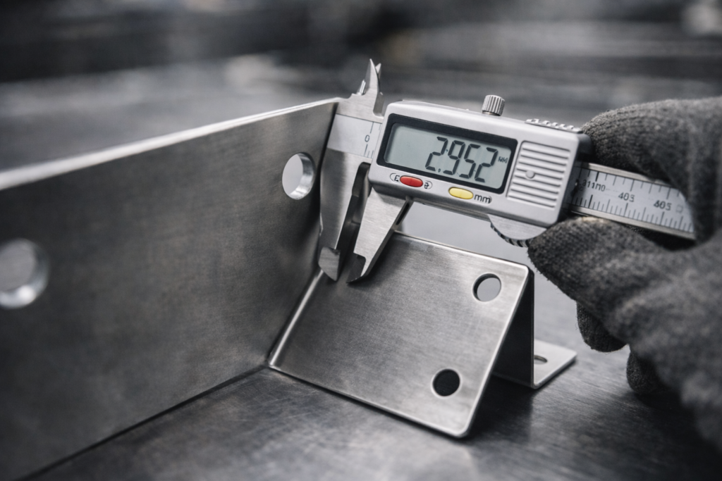
Tolerances: The Most Expensive Assumption in Sheet Metal Design
Buyers often receive drawings with tight tolerances applied everywhere. The intention is quality. The result is often instability.
Sheet metal processes introduce variation by nature. Tight tolerances reduce the manufacturing window, increasing scrap, rework, and inspection cost. In sourcing, this appears as higher quotes and longer lead times.
Where tolerance stack-up breaks programs
A single tight tolerance can be manageable. Multiple tight tolerances across multiple bends are far more risky.
Each bend adds variation. When several dimensions interact, the combined effect can exceed functional limits even when every step is technically within tolerance.
Practical tolerance strategy for RFQs
The most effective strategy is to define what is truly functional: mounting interfaces, alignment features, sealing surfaces, and critical hole patterns.
Non-functional dimensions should be relaxed. This improves yield and stabilizes cost without sacrificing performance.
Quick RFQ reference for buyers
| Design item | Impact on sourcing | Practical takeaway |
|---|---|---|
| Tight angle tolerances on multiple bends | Higher inspection, lower yield | Control only functional angles |
| Tight hole position near bends | Assembly risk | Increase distance or redesign interface |
| Tight flatness on formed panels | Difficult to guarantee | Specify functional flatness only |
| Tight tolerances on cosmetic edges | Added cost without value | Relax to reduce quote and lead time |
Why Designs That Work Once Often Fail in Mass Production
A prototype can be correct and still be a poor predictor of production success.
In low-volume builds, skilled operators can compensate through manual adjustment. In mass production, those interventions are unsustainable.

What changes as volume increases
As volume scales up, tool wear starts to matter. Batch-to-batch material variation becomes more noticeable. Fixture repeatability also becomes a dominant factor. That combination is what often creates the familiar “it worked before” surprise on reorders.
Yield and cost stability
For wholesale programs, yield directly affects unit cost and lead time.
Designing for scale means building robustness into geometry and tolerance strategy so normal variation does not break function.
What Good Sheet Metal Design Looks Like in Production, Not in CAD
Good sheet metal design is rarely impressive on screen. Its value shows on the shop floor.
Parts assemble without force. Hole patterns align without rework. Bends hit functional angles without repeated adjustment. Inspection focuses on what matters.
A sourcing-friendly definition of manufacturable
Manufacturable means the design can be produced repeatedly with standard controls, normal operators, and typical material variation.
The most effective sheet metal design decisions are often modest: sensible feature placement, realistic tolerances, and geometry that supports stiffness rather than fighting the process.
Questions Buyers Commonly Search After Problems Appear
Why does my supplier push back on tolerances for formed parts.
How can I prevent holes from drifting after bending.
Why did cost increase after prototype approval.
How do I reduce quality variation between batches.
These are procurement questions. They affect delivery, rework, and customer satisfaction.
Recognizing the root causes during quoting and DFM review prevents repeat issues across future orders.
Final Thought: Sheet Metal Design Is About Reducing Unknowns
The most practical way to think about sheet metal design is risk reduction.
When designs respect forming behavior, balance strength with manufacturability, and account for volume realities, sourcing becomes smoother. Quotes stabilize. Batches remain consistent. Reorders become predictable.
At YISHANG, we support wholesale buyers by reviewing drawings from a manufacturing perspective and identifying potential risks before production begins. If you would like a manufacturability review or a quotation, feel free to share your drawings and target volumes.
