CUSTOM ALUMINUM EXTRUSION | SAMPLE TO REPEAT ORDERS
Custom Aluminum Extrusion Components, Finished for Assembly.
Yishang supplies drawing-based aluminum profiles as finished industrial components—not simply raw lengths. We connect profile review, extrusion coordination, cutting, machining, surface finishing and metal assembly so frames, rails, posts and structural members arrive ready for the next operation.
Cut, machined and protected to the approved requirement
Sample first
Review the profile and assembly result before repeat orders
OEM & ODM
Drawing-based custom profiles and downstream fabrication
One project contact
Extrusion, metalwork, finishing and delivery kept connected
DESIGN THE PROFILE AROUND THE EQUIPMENT
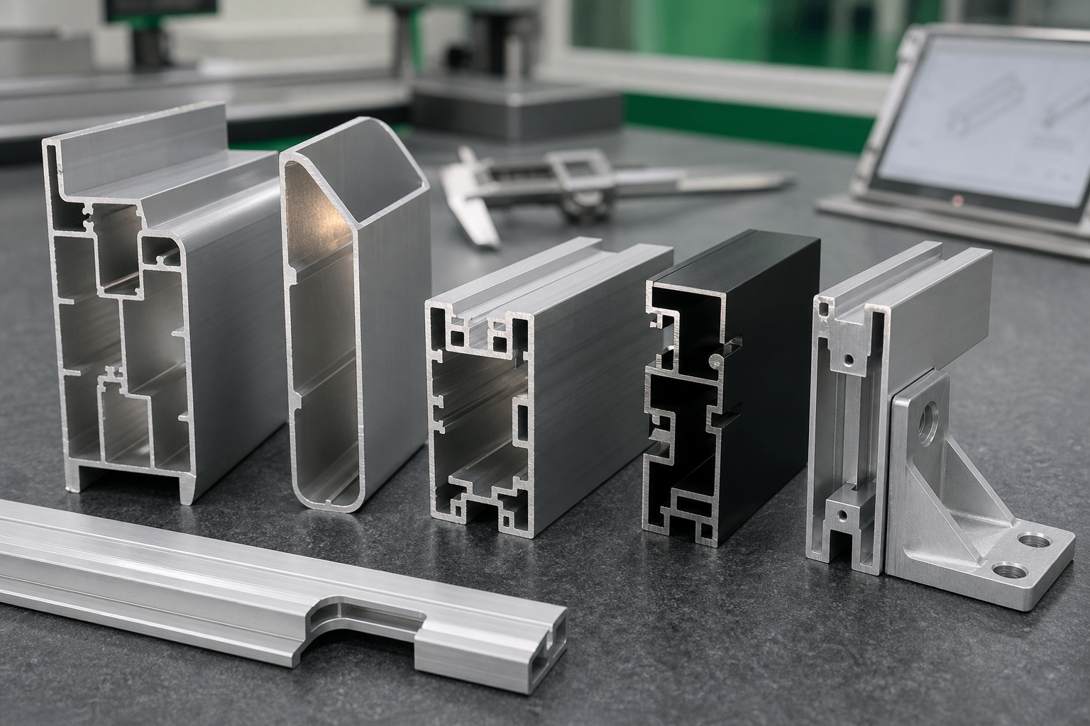
Put the Required Function Into the Cross-Section.
A well-planned profile can carry load, locate adjacent parts, guide assembly and create a finished edge at the same time. That can simplify the complete structure before any secondary process begins.
01
Carry the Load
Place material, webs and ribs where the frame or equipment structure needs stiffness instead of adding separate reinforcement later.
02
Locate Other Components
Build channels, shoulders, grooves and reference faces into the profile so panels, brackets and covers assemble consistently.
03
Reduce Separate Pieces
Combine mounting and alignment features where practical to reduce loose hardware, welding and avoidable fabrication steps.
04
Control Visible Edges
Plan the exposed surfaces, corner form and finish direction around how the finished equipment will look and be handled.
THE PROFILE IS ONLY THE START
Most Extrusion Problems Appear at the Interfaces.
Customers rarely reject a profile because aluminum was used. They reject it because the member is difficult to assemble, the holes miss, the frame is not square or the visible finish changes across a batch.
01
Bow, Twist and Flatness
WHAT IT CAUSES
Long members can pull a frame out of alignment or create gaps against panels.
HOW THE ROUTE CONTROLS IT
Identify the functional length, support points and assembly references before agreeing the inspection plan.
02
Cut and Hole Position Drift
WHAT IT CAUSES
Features measured from different ends can create stack-up during final assembly.
HOW THE ROUTE CONTROLS IT
Use an agreed datum scheme for cut length, holes, slots and machined interfaces.
03
Visible Finish Variation
WHAT IT CAUSES
Adjacent rails can look inconsistent after anodizing or powder coating.
HOW THE ROUTE CONTROLS IT
Define visible faces, acceptable appearance, handling protection and batch expectations before finishing.
04
Profile-to-Frame Mismatch
WHAT IT CAUSES
A profile can pass its own drawing and still fail inside the complete structure.
HOW THE ROUTE CONTROLS IT
Trial-fit representative members with the actual brackets, panels, fasteners and mating components.
BUILT FOR STRUCTURAL AND EQUIPMENT PROJECTS
Extruded Components With a Job to Do.
The focus is engineered profiles used inside repeat-production assemblies—not retail stock bars or decorative material sold by length.
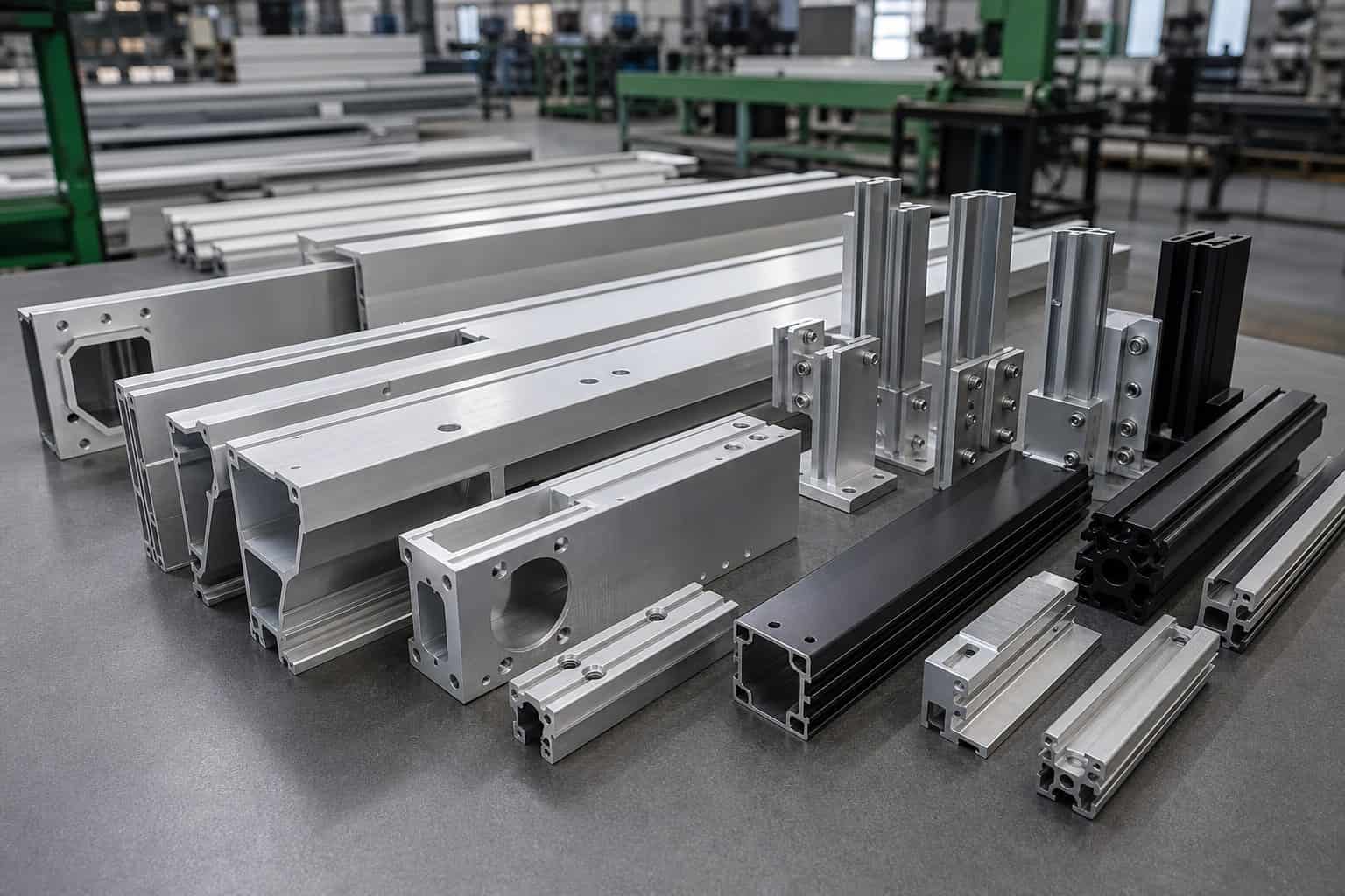
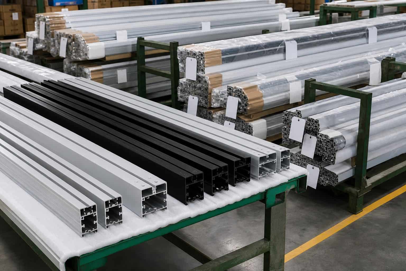
Representative engineered profile families shown after cutting and secondary processing.
01
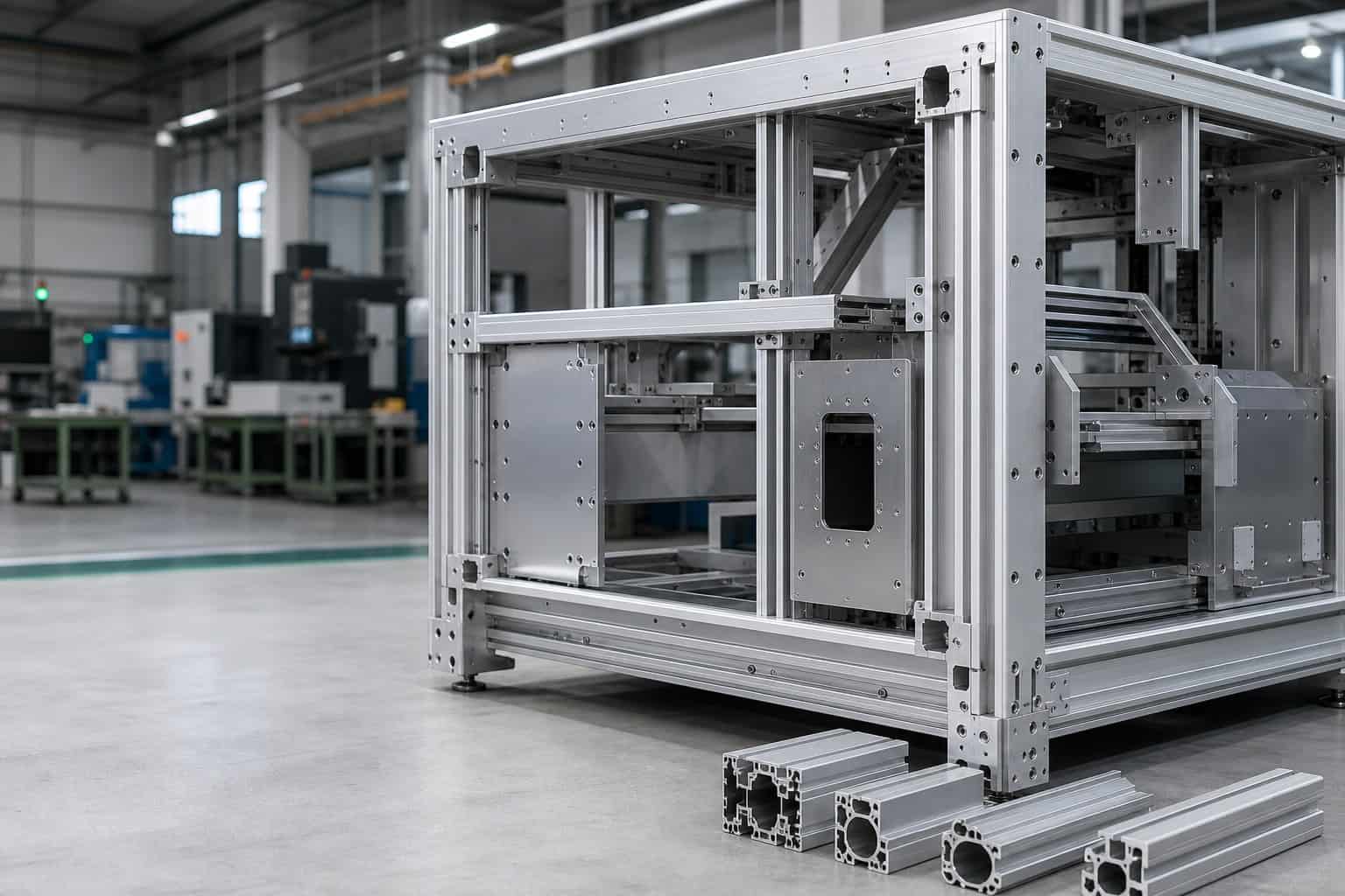
Equipment Frames and Crossmembers
Structural members prepared for machine bases, guards, workstations and industrial equipment.
02
Rails, Tracks and Guide Profiles
Custom sections with channels, mounting faces and machined features for controlled movement or positioning.
03
Posts, Beams and Support Members
Cut and processed profile components that form rigid equipment and enclosure structures.
04
Perimeter Frames and Panel Edges
Profiles that hold, protect or visually finish sheet-metal, glass, plastic or composite panels.
05
Mounting and Interface Profiles
Sections designed to connect brackets, covers, wiring, hardware and adjacent modules.
06
Machined Extrusion Components
Short or long profile components with holes, slots, pockets, threads and controlled end features.
THREE DECISIONS BEFORE TOOLING
Review the Cross-Section as Part of the Complete Assembly.
The strongest extrusion project begins with the end use. We review where the profile carries load, what it must connect to and which faces remain visible after assembly.
01
Structural path
Where does the load enter and where is the profile supported?
This guides wall placement, ribs, webs, hollow areas and the orientation used in the finished structure.
02
Assembly path
What must slide, locate, fasten or sit flush?
This connects the profile shape with fasteners, brackets, panels, access clearances and installation sequence.
03
Appearance path
Which surfaces will the customer see and touch?
This defines cosmetic faces, finish expectations, grain or texture direction, masking and protective packaging.
Solid, hollow and semi-hollow routes can be reviewed according to geometry, function, alloy and production feasibility. Final tooling direction is confirmed with the extrusion production partner.
POST-PROCESSING CREATES THE USABLE COMPONENT
Do Not Stop at a Cut Length.
Most equipment projects need a profile that already fits the drawing and assembly sequence. The downstream route is selected around geometry, volume, surface requirements and how the component will be installed.
Precision cutting
Square, angle or miter cuts with end condition and burr expectations defined.
CNC machining
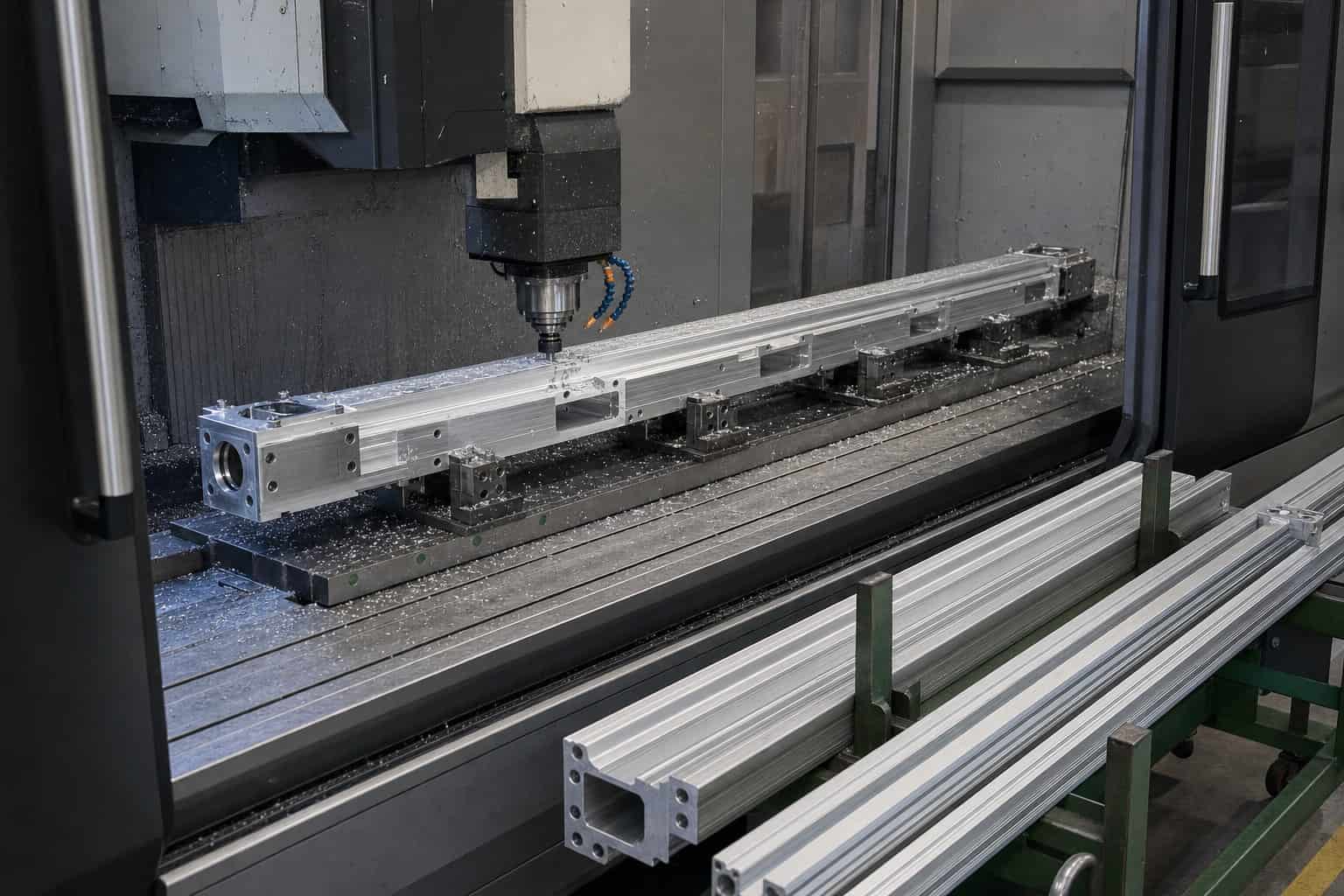
Pockets, counterbores, end features and controlled interfaces added after extrusion.
Drilling and tapping
Mounting holes, thread features and hardware locations connected to a common datum plan.
Punching and forming
Slots, openings or formed features reviewed where profile shape and alloy make the route suitable.
Joining and frame assembly
Extrusions connected with fabricated brackets, fasteners, welding or other approved joining methods.
Panels and hardware integration
Sheet-metal covers, plates, brackets, inserts and purchased hardware coordinated in one assembly context.
FINISH THE PART FOR ITS SERVICE ENVIRONMENT
Appearance, Protection and Assembly Must Agree.
The right finish depends on where the profile is used, which faces are visible and what must still fit after coating or treatment.
01
Clear or Color Anodizing
For controlled aluminum appearance and surface protection, with cosmetic faces and contact areas agreed before production.
02
Powder Coating
For durable color and coverage, with masking, grounding, film build and fit-sensitive areas considered.
03
Mill Finish With Protection
For concealed or further-processed components where handling marks and surface protection still need a defined standard.
04
Brushed or Machined Appearance
For selected visible faces where grain direction, machining pattern and transport protection form part of acceptance.
CONTROL THE PROFILE AS A STRUCTURAL MEMBER
Measure What Can Stop the Assembly.
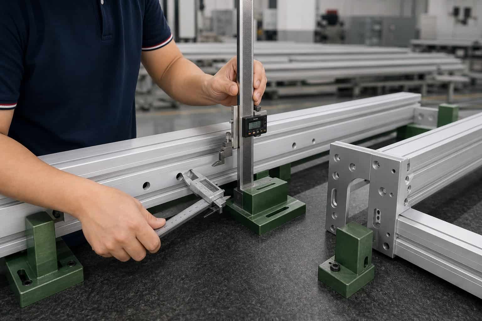
A long profile can meet individual dimensions yet still create problems when several members form one frame. Inspection is therefore linked to the actual interfaces and approved sample.
01
Cross-section and critical walls
Check agreed profile features and functional faces against the approved drawing and sample.
02
Straightness, bow and twist
Evaluate the member over the functional length and support condition used by the assembly.
03
Cut length and end condition
Control length, squareness or angle, burrs and any reference established from the end face.
04
Machined feature position
Verify holes, slots, threads and pockets from the datum scheme that matters to installation.
05
Surface and finish consistency
Review visible faces, shade or texture expectations, handling marks and protected areas.
06
Representative assembly fit
Trial-fit profiles with mating panels, brackets and hardware when these are included in the project.
ISO 9001
Quality management system
RoHS
Restricted-substance requirements where applicable
START WITH THE INFORMATION THAT CHANGES THE ROUTE
Four Things Are Enough for a Useful First Review.
You do not need to prepare a long questionnaire. Send the current drawing and the few project facts that decide tooling, post-processing and delivery.
01
Profile drawing
Cross-section, overall component drawing, critical dimensions and identified datums.
02
Finished-component requirements
Cut length, holes, threads, machining, joining, visible faces and finish.
03
Assembly context
Mating panels, brackets, fasteners, loads and the interfaces that cannot move.
04
Sample and order plan
Sample quantity, expected repeat quantity, target timing and packing needs.
PRACTICAL QUESTIONS
Can we begin with samples?
Yes. A sample or production-intent component can be reviewed before repeat orders are released.
Do you sell standard aluminum profiles by length?
The page is focused on drawing-based industrial components. Standard profiles can be reviewed when they still require cutting, machining, finishing or assembly work.
Is extrusion performed inside Yishang's factory?
The extrusion is coordinated through a suitable production partner. Yishang manages the project contact and connects it with the approved secondary processing, metalwork, inspection and delivery scope.
CUSTOM PROFILES, FINISHED FOR THE REAL ASSEMBLY
Send the Profile Drawing and Show Us Where It Must Fit.
We will review the cross-section, downstream work and assembly interfaces, then return with a practical sample-to-production route.