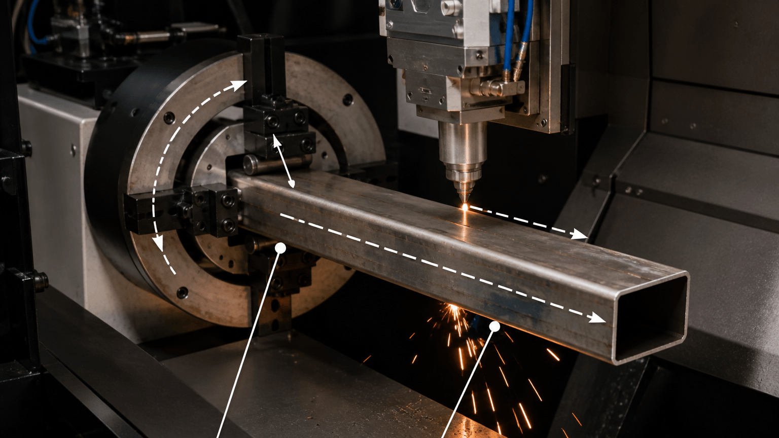
Short answer: Precision tube laser cutting is CNC laser processing of a supported hollow or open-section profile while the workpiece is positioned and commonly rotated or indexed relative to the cutting head. It can create through-holes, slots, contours, notches, and some angled ends without manual refixturing between faces. Precision is drawing-defined rather than universal: the result depends on machine configuration, material grade, wall thickness, laser parameters, workholding, feature geometry, and the agreed inspection criteria.
What precision tube laser cutting means in practice
For an OEM deciding whether a tube component can be quoted as one laser-cut part, the key question is not simply whether a supplier owns a laser. Precision tube laser cutting is CNC laser processing of a supported hollow or open-section profile while the workpiece is positioned and commonly rotated or indexed relative to the cutting head.
Depending on the equipment, supported profiles may include round, square, rectangular, channel, or another hollow or open section that fits the machine’s workholding and access requirements. The process can produce through-holes, slots, perimeter contours, copes, notches, and some angled ends for frames, enclosures, cabinets, and welded assemblies. However, the word precision does not establish a universal tolerance; it means that feature location, profile orientation, edge condition, and other requirements are controlled against a specified drawing and inspection method.
From CAD/CAM program to finished tube
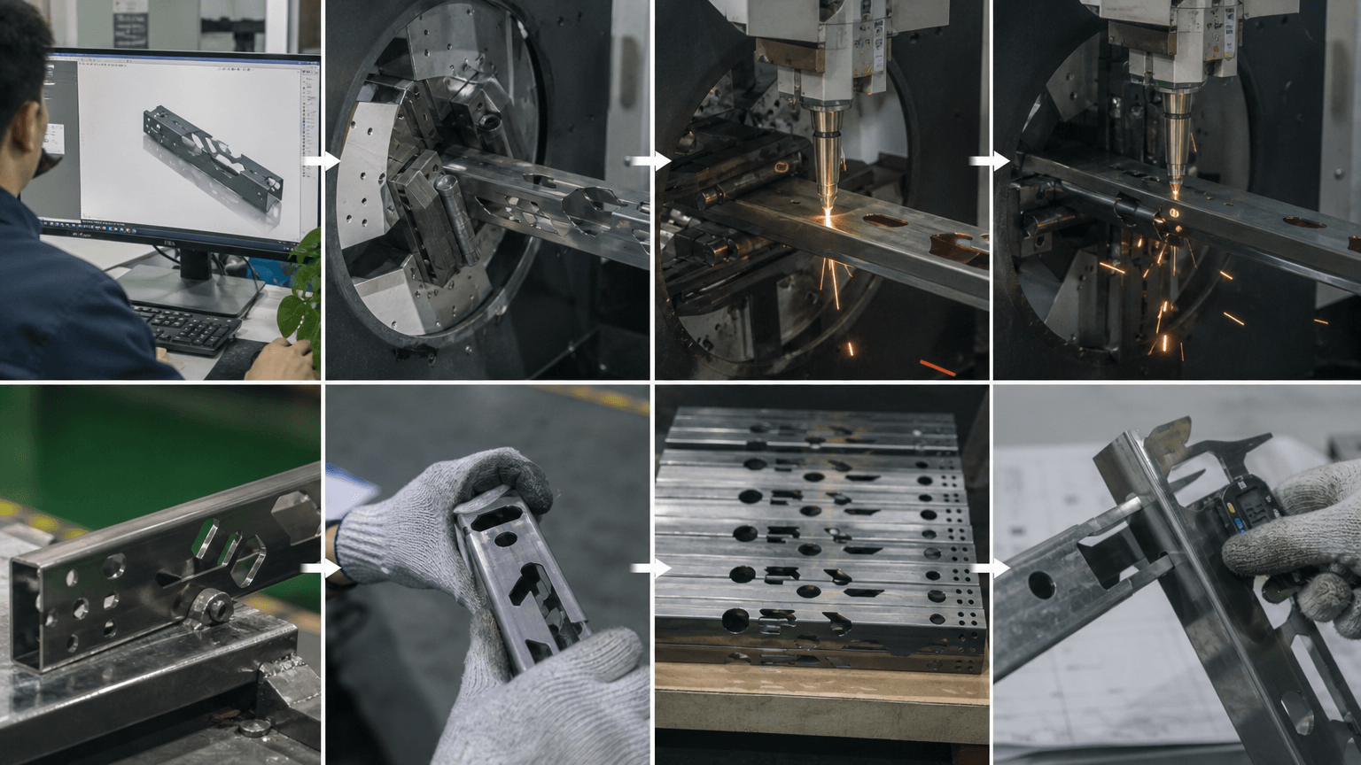
When a drawing places holes on several faces or requires a shaped tube end, the cutting program must coordinate profile movement with the feature sequence. A tube laser job is therefore more than a flat-sheet program wrapped around a tube. The main stages are:
- CAD/CAM preparation: The drawing or model is converted into a cutting program. Profile orientation, feature sequence, pierce locations, lead-ins, nesting, and rotary or indexing movements are reviewed.
- Loading and clamping: Raw stock is placed in a chuck or collet system. Clamps, steady rests, and supports must hold the section without crushing it, shifting its datum, or blocking required features.
- Alignment and movement: The control system aligns the profile and coordinates longitudinal travel with rotation or indexed repositioning. The required motion depends on the profile and feature pattern.
- Piercing and cutting: The focused laser heats and melts the material along the programmed path. Assist gas expels molten material through the kerf, while focus, power, speed, nozzle condition, and gas selection affect the process window.
- Heat and cut-order control: Closely spaced features, thin walls, and long sections may need a planned sequence to limit heat concentration, vibration, or local deformation.
- Unloading and follow-up: The cut part is removed and checked. Deburring, cleaning, drilling, tapping, boring, bending, milling, turning, welding, coating, polishing, assembly, packaging, or other secondary work may follow.
Process route: CAD/CAM → load and clamp → rotate or index profile → pierce → assist-gas cutting → unload → deburr, inspect, or complete secondary operations.
Tube laser cutting is one operation within a broader custom sheet metal fabrication workflow. The commercial label does not make cutting, machining, bending, welding, finishing, and assembly interchangeable. The laser does not automatically create a thread, tapped hole, precision bore, bend, weld, or finished assembly. For general process context, see the laser cutting service route.
| Process | Primary role | Boundary compared with tube laser cutting |
|---|---|---|
| Flat-sheet laser | Cuts planar sheet profiles and holes | Does not automatically provide rotary access to multiple tube faces. |
| CNC punching | Uses punches and dies for planar holes or forms | Tool access, die clearance, and profile compatibility differ. |
| Tube bending or roll forming | Changes the tube or strip shape along its length | Laser cutting removes material; it does not bend the profile. |
| Drilling | Creates controlled round holes with a cutting tool | May be required when the drawing calls for a machined hole or a blind feature. |
| Tapping | Creates internal threads | Must be specified as a secondary operation after a suitable opening is cut or drilled. |
| Boring or milling | Produces machined bores, pockets, faces, or interfaces | Uses CNC tooling and separate workholding rather than a laser path. |
| Turning | Machines rotational features or tube-end interfaces | Uses a lathe-type process and a different datum and tooling strategy. |
| Plasma or saw cutting | Separates plate or profile stock | Thermal input, feature detail, edge condition, and setup must be compared for the actual job. |
| Welding | Joins cut or formed components | Follows cutting when the design requires a frame, bracket, or welded assembly. |
Tube-laser DFM: dimensions and features that control feasibility
At the quoting stage, a profile may look simple while a feature near the tube end or a thin wall creates the main production risk. Outside dimensions or section size, wall thickness, cut length, material, rotary-axis configuration, support, and the location of every feature influence the achievable result. A generic online chart cannot establish a safe minimum hole, slot, wall, tolerance, maximum diameter, or maximum length for every machine and material.
- Profile and access: Round, square, rectangular, and open sections present different clamping and cutting conditions. The profile must fit the chuck, steady rests, machine envelope, and cutting-head access.
- Wall thickness and length: Thin walls are more sensitive to piercing, heat concentration, clamping force, vibration, and local collapse. Long sections can deflect or oscillate and may need additional support or a changed cut sequence.
- Holes and edge distance: A small hole close to an edge can distort the remaining wall, leave a more difficult edge condition, or weaken the section. Hole diameter and hole-to-edge distance should be checked against the actual material and profile.
- Slots and corners: Narrow slots, closely spaced openings, sharp internal corners, and acute transitions can concentrate heat or retain dross. Reliefs, altered geometry, or sample validation may be appropriate.
- Angled and end features: Angled cuts and compound contours depend on rotary coordination, support, and access. Features near the tube ends may fall inside a chuck or clamp blind zone, requiring extra stock or a sacrificial lead-in or lead-out area.
- Workholding and automation: Clamping marks, part movement, and support-point clearance can affect visible surfaces and feature position. Automated loading or support equipment may improve handling consistency and schedule, but its presence does not prove fit for a particular profile.
These decisions interact with laser power, focus, nozzle configuration, assist gas, and cutting speed. Power is one process input, not proof of a universal tube-processing range, and a rotary-axis configuration may reach some faces or angles but not every geometry. For long, thin-wall, reflective, or unusually shaped profiles, a representative sample is more useful than an unsupported minimum-feature claim.
Tube-laser fit matrix
| Feature or requirement | Tube-laser fit | Design or purchasing action |
|---|---|---|
| Through-holes on accessible faces | Suitable | Confirm profile support, datums, position requirements, and inspection access. |
| Slots or repeated openings | Validate with a sample | Review proportion, spacing, wall thickness, heat concentration, and burr limits. |
| Perimeter contours, copes, and notches | Suitable | Check rotary access, profile orientation, and later fit-up. |
| Angled ends or compound contours | Validate with a sample | Confirm rotary control, support, angular acceptance, and end deformation risk. |
| Features close to tube ends | Validate with a sample | Identify chuck and clamp blind zones and define trim stock if needed. |
| Threads, tapped holes, and precision bores | Plan a secondary operation | Specify drilling, tapping, boring, reaming, milling, or another machining route. |
| Bends, welds, and assembled joints | Plan a secondary operation | Separate cutting, forming, welding, finishing, and assembly requirements. |
Material, laser source, and assist gas
Two otherwise identical tube RFQs can require different parameter windows when the alloy, temper, surface condition, or wall thickness changes. Mild steel, stainless steel, aluminum, copper, and other supported metals differ in reflectivity, thermal conductivity, and response to piercing and cutting. Settings developed for flat sheet or another alloy should therefore be qualified rather than transferred automatically to a tube.
CO2 systems use a gas-discharge laser with mirror-based beam delivery, while fiber systems use a solid-state architecture with optical-fiber beam delivery. The source architecture affects absorption, optics, maintenance, and parameter development, but a generic fiber-laser specification does not prove that a supplier can process every round, square, rectangular, or open-section profile. Equipment fit and representative validation remain separate questions.
| Assist gas | Potential effect | Downstream consideration |
|---|---|---|
| Oxygen | In suitable steels, oxidation-assisted cutting may affect cutting speed, burr formation, edge color, and dross. | Oxide residue or discoloration may need removal before welding, polishing, or coating. |
| Nitrogen | An inert environment can reduce oxidation and change edge appearance, burr behavior, gas use, and the practical parameter window. | Consider it when low oxidation matters, subject to the actual material and cost basis. |
| Compressed air | Its mixed composition and moisture or oil control can influence speed, burrs, oxidation, and edge consistency. | Confirm filtration and the required surface condition before welding or finishing. |
Heat-affected areas and oxide residue may matter especially on visible faces or welded joints. The drawing should state whether cleaning, deburring, polishing, coating preparation, or a particular edge appearance is required. For early material planning, the materials information page can be a reference, but the actual grade and condition belong on the project documentation.
Inspecting tube-laser parts against the drawing
If a tube component must fit a welded frame, align with a mating part, or present a visible finished face, a clean-looking cut is not enough evidence. Acceptance should begin with the drawing, not with a supplier’s unsupported use of the word precision. A practical verification workflow is:
- Set the inspection basis: Identify datums, profile orientation, critical dimensions, cut length, hole and slot positions, angular features, and visible-face requirements.
- Approve a sample: Use a first-article or prototype review when the material, profile, thin wall, tolerance, or feature pattern creates meaningful production risk.
- Perform in-process checks: Confirm alignment, feature orientation, clamping marks, support, and critical dimensions on initial pieces or during production as agreed.
- Inspect the cut edge: Check burrs, dross, oxidation, discoloration, distortion, edge damage, and heat-affected areas against stated acceptance limits.
- Complete final records: Record critical measurements, methods, results, and material identification or batch traceability where the project requires them. Define what is checked for each production batch.
Measurement method should match feature size, access, tolerance, and part length. A hole position on a round tube may need a different fixture or datum strategy from a hole on a square section. Request representative inspection records or a first-article report, and ask which checks are in-process versus final. The supplier’s quality control plan should make those responsibilities clear.
Cost, lead time, and supplier fit
A quoted cutting rate can hide the inputs that determine the actual cost of a tube component. The total may include tube purchasing or cut-length constraints, nesting and material utilization, programming, setup, workholding, assist gas, loading, scrap, deburring, secondary machining, bending, welding, finishing, assembly, packaging, and shipping. Quantity changes how setup, programming, nesting, and capacity are distributed across the parts.
Lead time can also depend on material availability, prototype approval, parameter validation, machining, welding, coating, polishing, inspection, packaging, capacity, and transport. Ask the supplier to separate approval and secondary-operation dependencies rather than hiding them inside a single delivery assumption.
A supplier experienced in flat-sheet work may still need to route some tube features through drilling, tapping, milling, turning, bending, welding, or another process. Evaluate the actual process route instead of treating general custom sheet metal fabrication experience as proof of tube-laser capability.
| Supplier review area | Evidence or question for the OEM buyer |
|---|---|
| Equipment and workholding fit | Can the supplier demonstrate fit for the profile category, dimensions, wall thickness, cut length, rotary or indexing needs, supports, and loading assumptions? |
| Sample validation | Will the actual material and representative geometry be trialed, with critical features measured before batch release? |
| Inspection and traceability | Are drawing-linked inspection records, edge acceptance criteria, and material-batch records available where required? |
| Planning and quotation | Are material availability, minimum-order assumptions, programming, fixtures, capacity, secondary operations, packaging, and delivery milestones stated separately? |
For a useful tube laser RFQ, provide:
- 2D drawing and, when available, a 3D model;
- Profile type, outside dimensions, wall thickness, cut length, material grade, and temper;
- Datums, critical dimensions, hole and slot tolerances, angular requirements, and visible-face expectations;
- Edge-quality, burr, oxidation, discoloration, and distortion limits;
- Required deburring, drilling, tapping, boring, bending, welding, coating, polishing, assembly, or other secondary operations;
- Prototype and batch quantities, packaging requirements, and target delivery window.
Frequently Asked Questions
These questions address common drawing and quoting decisions before an OEM releases a tube-laser RFQ. The right answer depends on the specified profile, material, tolerances, finish, quantity, and inspection basis.
Does precision tube laser cutting mean that the tube is bent during the laser process?
No. The tube is positioned and commonly rotated or indexed so the cutting head can reach different faces. Bending and roll forming change the tube’s shape and are separate operations.
Can a tube laser cut holes and slots in both round and square tubing?
It can when the machine supports the profile and the features are accessible. Round and square sections behave differently during clamping, rotation, piercing, and inspection, so the actual material and wall thickness should be validated.
How should an OEM specify tube-laser precision when no universal tolerance applies?
Define datums, profile orientation, critical dimensions, hole and slot positions, angular requirements, cut length, edge-quality limits, burr or oxidation limits, material condition, and the inspection method. Use sample or first-article approval for higher-risk geometry.
When are drilling, tapping, boring, or CNC machining still required after tube laser cutting?
They are normally required for threads, tapped holes, precision bores, controlled countersinks, blind holes, machined faces, or other interfaces that the laser does not create directly. Milling or turning may also be needed at a tube end.
What should a supplier demonstrate before quoting a long, thin-wall, or complex-profile tube component?
Ask for demonstrated equipment and workholding fit, experience with the specified profile and wall condition, a representative sample or validation plan, inspection evidence, material traceability, and a production plan covering secondary operations, capacity, packaging, and delivery assumptions.