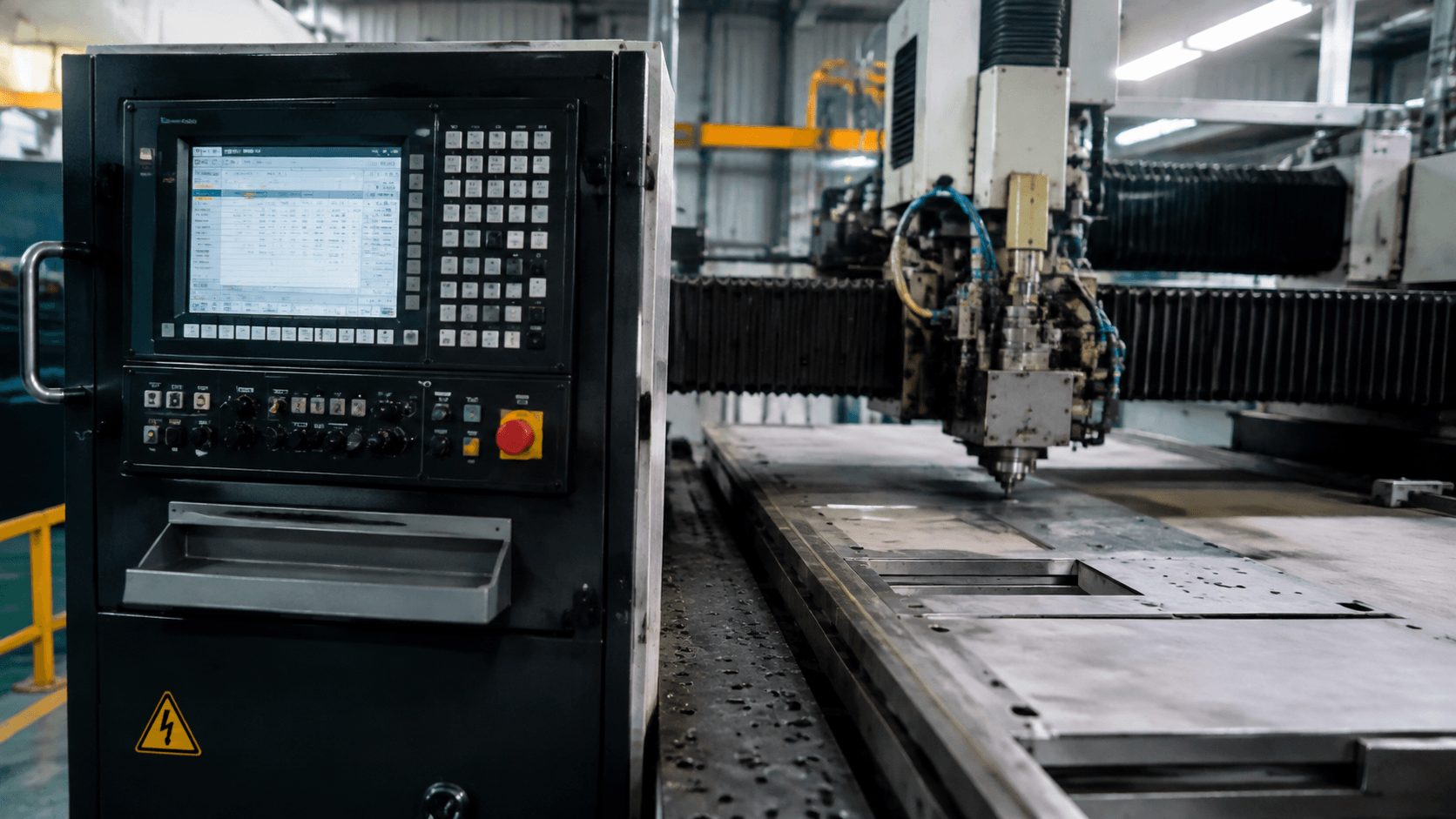
A computer numerical control system is the hardware and software that interprets a numerical program and commands machine movements and process functions. It is the control layer—not the complete machine or a guarantee of finished-part accuracy—and its role differs between sheet laser cutting, CNC punching, press-brake bending, and subtractive CNC machining.
In brief: The controller reads the program, coordinates axes and process states, and exchanges information with drives, motors, and feedback devices where provided. Machine mechanics, tooling, material, setup, and inspection determine whether the resulting part meets its requirements.
For an OEM buyer comparing routes for a bracket, enclosure, panel, or machined interface, the phrase CNC controlled identifies the command method but leaves important questions open. It does not by itself show whether the process suits the geometry, material, surface requirement, tolerance, or production quantity. The sections below separate the control layer from the machine and compare what CNC directs in four metalworking processes.
Computer Numerical Control System Defined
When a supplier reviews a drawing package, the word CNC may describe several different operations. The control system interprets numerical instructions and coordinates movement and process functions; the machine mechanics and process hardware then perform the physical cutting, forming, or material removal.
Instructions can define positions, movement rates, operation sequences, tool selections, and process states. Programming may use standardized commands, machine-specific formats, conversational input, or post-processed output, so the workflow varies by machine and application.
- CNC control system: Controller, program interface, motion-control functions, drives, and feedback functions where used.
- Complete CNC machine: Frame, guides, actuators, work area, process hardware, guarding, mechanical systems, and the CNC control.
- CAM or nesting software: Tools for creating paths, arranging sheet profiles, planning operations, and preparing machine instructions.
- Tooling and workholding: Punches, dies, cutters, fixtures, clamps, supports, and locating devices that interact with or restrain the material.
- Manufacturing process: The physical method used to cut, form, or remove material. Numerical control directs the method but does not change its underlying mechanics.
Laser cutting uses a focused heat source, punching uses tool-and-die action, press-brake bending plastically forms sheet, and CNC machining removes stock with cutting tools. Numerical control is also used outside metalworking, but these applications should not be treated as interchangeable.
From Program Commands to Machine Motion
For a sheet-metal setup, the production result depends on more than the loaded program. CNC equipment combines digital commands with electrical motion control, machine mechanics, process hardware, and operator decisions, while the exact architecture varies by machine type.
- Controller: Interprets the program, calculates coordinated movement, manages sequences, and communicates with drives and machine functions.
- Operator panel or HMI: Lets an operator load, select, review, simulate, and start programs while presenting operating information and alarms.
- Drives and motors: Drives regulate motor output; motors provide the rotary or linear motion used by tables, heads, rams, turrets, spindles, or gauges.
- Axes and mechanics: Guides, bearings, transmissions, frames, tables, rams, and spindles convert motor output into useful movement.
- Sensors and encoders: Where fitted, these report position or machine conditions. Closed-loop control compares commanded and detected conditions; open-loop arrangements may operate without continuous position feedback.
- Process controls: Depending on the equipment, CNC may coordinate laser output, punch actuation, spindle speed, feed rate, tool selection, back-gauge position, or press-brake ram movement.
The operator establishes material identity, tooling, workholding, datums, offsets, and safe setup. Numerical control automates programmed movement, but process knowledge and setup verification remain part of production control.
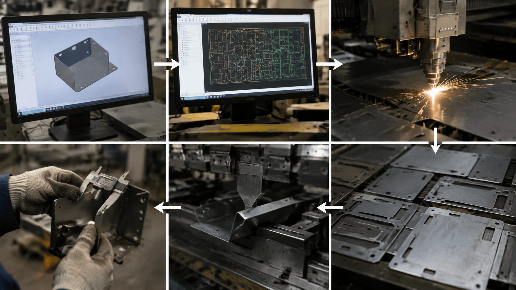
Digital Design to Inspected Component
An approved drawing still has to be translated into a workable operation before a controller can move a tool or cutting head. The path from design intent to an inspected bracket, panel, blank, or machined feature typically includes these stages:
- Define the design: A 2D drawing or 3D model communicates geometry, material, datums, critical features, and tolerances.
- Plan the operation: CAM, nesting, offline programming, or machine-level programming develops a cutting path, punch sequence, bend sequence, or machining plan.
- Prepare instructions: Where applicable, a post-processor converts the plan into a format suited to the intended controller and machine configuration.
- Set up the work: The team selects tooling, fixtures, clamps, supports, orientation, work offsets, and locating methods.
- Check the sequence: Simulation, graphical review, dry running, or a controlled first operation may check travel, clearance, orientation, and tool access.
- Execute: The controller commands axis movement and process actions such as feed changes, tool selection, punch firing, laser activation, spindle operation, or bend positioning.
- Inspect: The produced features are measured against the drawing using the defined datums and inspection method.
Machine feedback and part inspection answer different questions. An encoder can report axis position during motion, while inspection evaluates the actual feature. The controller should not be expected to identify an unsuitable drawing, wrong material, poor setup, worn tool, or inappropriate process parameters without a defined correction strategy.
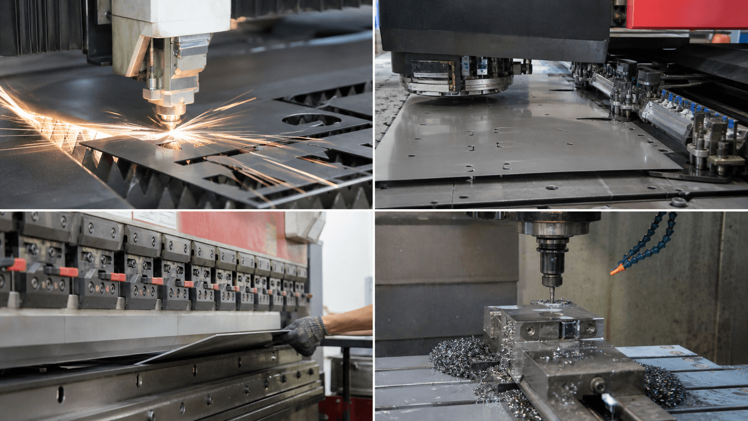
What the CNC System Controls in Each Metalworking Process
Two suppliers may both describe their equipment as CNC controlled while directing very different physical actions. This matrix helps an OEM team select a process category rather than compare the CNC label as though it established the same geometry, tooling, or capacity in every case.
| Process | CNC-controlled action | Typical geometry or output | Important tooling and setup variables | How to interpret the CNC label |
|---|---|---|---|---|
| Sheet laser cutting | Head or table movement, laser state, and related process commands. | Flat profiles, holes, slots, cutouts, and blanks for later operations. | Material, focus, heat input, support, consumables where applicable, and process parameters. | Material or thickness suitability, edge condition, heat effects, and burr level require process-specific evidence. See laser cutting. |
| CNC punching | Sheet positioning, turret or tool selection, hit sequence, and punch actuation. | Holes, slots, notches, perforations, cutouts, and formed features supported by the tooling. | Punch and die geometry, clearance, tool condition, hit pattern, support, and material movement. | Tooling limits, burrs, tool marks, distortion, and geometry constraints still need review. See CNC punching. |
| Press-brake bending | Back-gauge position, ram or beam movement, bend sequence, and depth or angle strategy where available. | Flanges, channels, brackets, panels, hems, and other formed sheet-metal shapes. | Punch and die selection, bend allowance, material direction, alignment, setup, and springback compensation. | Programmed ram position alone is not evidence of the final angle or flange dimension. See metal bending. |
| Subtractive CNC machining | Cutting-axis path, spindle and tool operation, feed, and tool sequence. | Bores, pockets, drilled holes, milled faces, contours, and other removed-stock features. | Cutters, fixtures, stock allowance, tool condition, datums, cutting parameters, and rigidity. | Machining uses a different material-removal process, toolset, and feature-access logic from laser cutting or punching. See CNC machining. |
These remain distinct production steps. A machined interface part may join a sheet-metal assembly, while welding, finishing, and assembly follow as downstream operations rather than becoming CNC cutting or forming. Material range, thickness, dimensions, geometry, output rate, and tolerance depend on the actual equipment and setup, so the CNC label alone provides limited evidence of production capacity.
Machine Specifications Versus Finished-Part Results
A buyer may see a controller resolution or positioning figure in a capability statement and mistake it for the finished-part tolerance. Command resolution describes the smallest numerical increment the control can process or issue; it describes instruction granularity rather than the achieved feature. Positioning accuracy concerns the difference between commanded and achieved position under stated conditions. Repeatability concerns how consistently a machine returns to a position. Finished-part tolerance applies to a specified feature after the complete process.
Results also reflect backlash or mechanical condition, calibration, thermal movement, workholding, fixture rigidity, tool condition, tool deflection, sheet movement, burr formation, heat input, material behavior, and setup. Laser cutting can introduce thermal effects, punching depends on tool-and-die condition and clearance, bending responds to material springback, and machining is affected by cutter condition, stock, datums, and rigidity.
Surface quality needs the same care: a programmed path does not establish a suitable cut edge, punched feature, formed surface, or machined finish. An accuracy or finish claim needs the feature, material and process, datum scheme, part condition, measurement method, environmental conditions, and sampling plan.
Interpreting a Supplier’s CNC Capability Statement
If a supplier says a bracket or enclosure will be CNC produced, first ask which operation creates each critical feature. The relevant route may be laser cutting, punching, bending, machining, or a combination followed by welding, finishing, or assembly.
Review the proposed route against the material grade, sheet thickness, machine envelope, blank dimensions, geometry, tooling, workholding, software compatibility, datums, critical dimensions, edge or surface requirements, inspection state, batch quantity, and production-validation plan. CAD data may still require nesting, CAM preparation, post-processing, and manual process decisions before execution.
These questions differ from buying a CNC machine. An equipment buyer may assess controller support, software licensing, training, maintenance, spare parts, service response, downtime, and lifecycle cost. An OEM sourcing finished parts should focus on whether the supplier has selected and controlled a suitable process route.
Yishang is a B2B OEM and ODM custom manufacturer, not a CNC control-system or machine-tool supplier. Its sheet-metal process review can consider laser cutting, CNC punching, bending, welding, finishing, and assembly. A separately machined part should be scoped against its own requirements and its interface with the sheet-metal assembly.
Request a Process-Route Review
To discuss a prototype or batch-production route, send Yishang your 2D drawings and available 3D files, material grade and sheet thickness, critical dimensions and tolerances, inspection requirements, finish expectations, required quantity, expected repeat-order volume, and the required bending, welding, finishing, or assembly scope. Yishang can review whether laser cutting, CNC punching, bending, welding, finishing, and assembly form a suitable route for the sheet-metal product.
Where RFQ Assumptions Create Cost and Production Risk
Many sheet metal fabrication problems begin before production starts. If drawings, tolerances, finish expectations, material grades, or assembly requirements are unclear, suppliers may quote based on different assumptions. That can make prices difficult to compare and may lead to rework, cosmetic rejection, assembly misalignment, or production delays later.
For OEM buyers, the goal is not simply to request the lowest price. The goal is to make sure each supplier is quoting the same manufacturing reality. Before confirming an order, clarify which dimensions are fit-critical, which surfaces are cosmetic, whether prototypes must match batch-production conditions, and how finished parts will be inspected.
Frequently Asked Questions
What laser cutting precision details should buyers define before requesting a quote?
Buyers should define the functional requirement, drawing notes, critical dimensions, material or process expectations, and any inspection points related to laser cutting precision. This helps suppliers quote the same manufacturing scope instead of making different assumptions.
How can cut hole locations affect cost, fit, or lead time?
cut hole locations can change tooling, forming, welding, finishing, inspection, or rework requirements. If buyers do not clarify it early, two supplier quotes may look comparable while covering different production risks.
Why should bend-to-hole dimensions be reviewed before prototype approval?
bend-to-hole dimensions may look acceptable on a single sample but become harder to control during batch production. Buyers should confirm whether the prototype reflects the same process, finish, and inspection conditions expected for production.
What inspection points matter most for computer numerical control system projects?
Important inspection points usually include fit-critical dimensions, holes or mating areas, cosmetic surfaces, finish build-up, welded or formed features, and any dimensions that affect downstream assembly. These points should appear in the RFQ or drawing notes.
How can buyers reduce batch consistency risk before batch production?
Buyers can reduce risk by clarifying drawings, locking key material and finish assumptions, defining inspection timing, approving a representative sample, and confirming which dimensions or surfaces require tighter process control.
How can Yishang help review computer numerical control system requirements?
Yishang can review drawings, RFQ notes, material requirements, tolerance expectations, finish details, samples, and assembly needs to identify unclear assumptions before quoting or batch production.