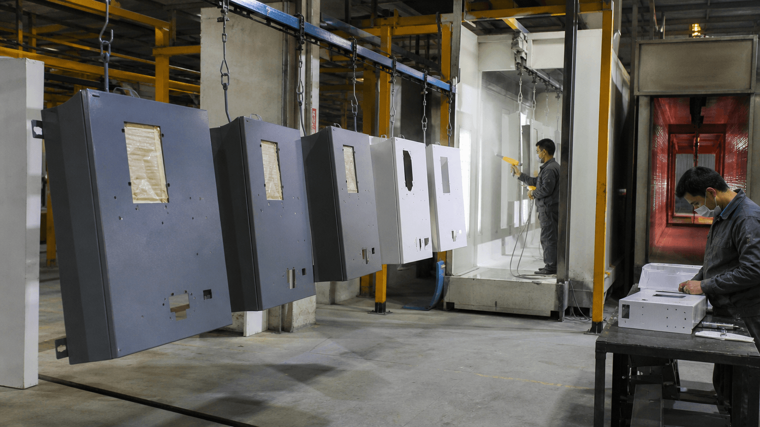
Powder paint in industrial metal manufacturing
Powder paint usually means a dry coating powder applied to a prepared metal surface and thermally fused or cured into a continuous film. For an OEM buyer reviewing a drawing, sample, or finish requirement, powder coating is the more precise process term; powder paint is the common purchasing and search phrase. The finished part depends on the powder chemistry, substrate, pretreatment, application, cure, and inspection—not on the word powder alone.
Powder coating is different from wet liquid paint, aluminum anodizing, and metal plating. It is also not automatically equivalent to applying powder to plastic. A non-metal substrate requires a separate review of its electrostatic behavior, heat tolerance, and compatibility with the coating system.
How the industrial powder-coating workflow is controlled
For a fabricated sheet-metal part, each production stage controls a different source of finish failure. A problem introduced during cleaning, welding, masking, spraying, or heating may not become visible until final inspection or assembly, so fabrication, coating, and inspection requirements need to be coordinated from the start.
- Assess the substrate. Confirm the metal grade or alloy, thickness, surface condition, weld areas, damage, residues, and zones that must remain uncoated.
- Clean and degrease. Remove oil, shop dirt, fingerprints, drawing compounds, and other contamination that could interfere with adhesion or finish quality.
- Pretreat and dry. Select a mechanical or chemical preparation route compatible with the metal, surface condition, powder system, and service environment. The part must be suitably dry before application.
- Mask, hang, and ground. Plugs, caps, films, or other masking protect threads, datums, press-fit areas, and mating surfaces. The hanger must also provide a reliable electrical path between the workpiece and ground.
- Apply the powder. In a common electrostatic process, charged powder is directed toward the grounded part. Gun access, part orientation, deposition settings, and geometry all affect coverage.
- Cure in the oven. Heat causes the powder to melt and flow and, for thermosetting systems, to cure into the specified film. The applicable powder technical data sheet defines the required cure relationship.
- Cool and inspect. Once the part reaches a suitable handling condition, inspect its appearance, coverage, functional interfaces, and any agreed film or performance characteristics.
Cure control matters: The oven display setting alone does not prove that the coating cured correctly. Actual workpiece temperature, heating time, time at temperature, load arrangement, and oven uniformity must all be considered. One temperature-and-time combination cannot be treated as universal across different powder chemistries, metal thicknesses, and part geometries.
Powder should also be stored and handled according to the supplier’s requirements. Moisture, contamination, unsuitable storage conditions, or uncontrolled material mixing can affect deposition, flow, appearance, and process repeatability.
How substrate and geometry affect the result
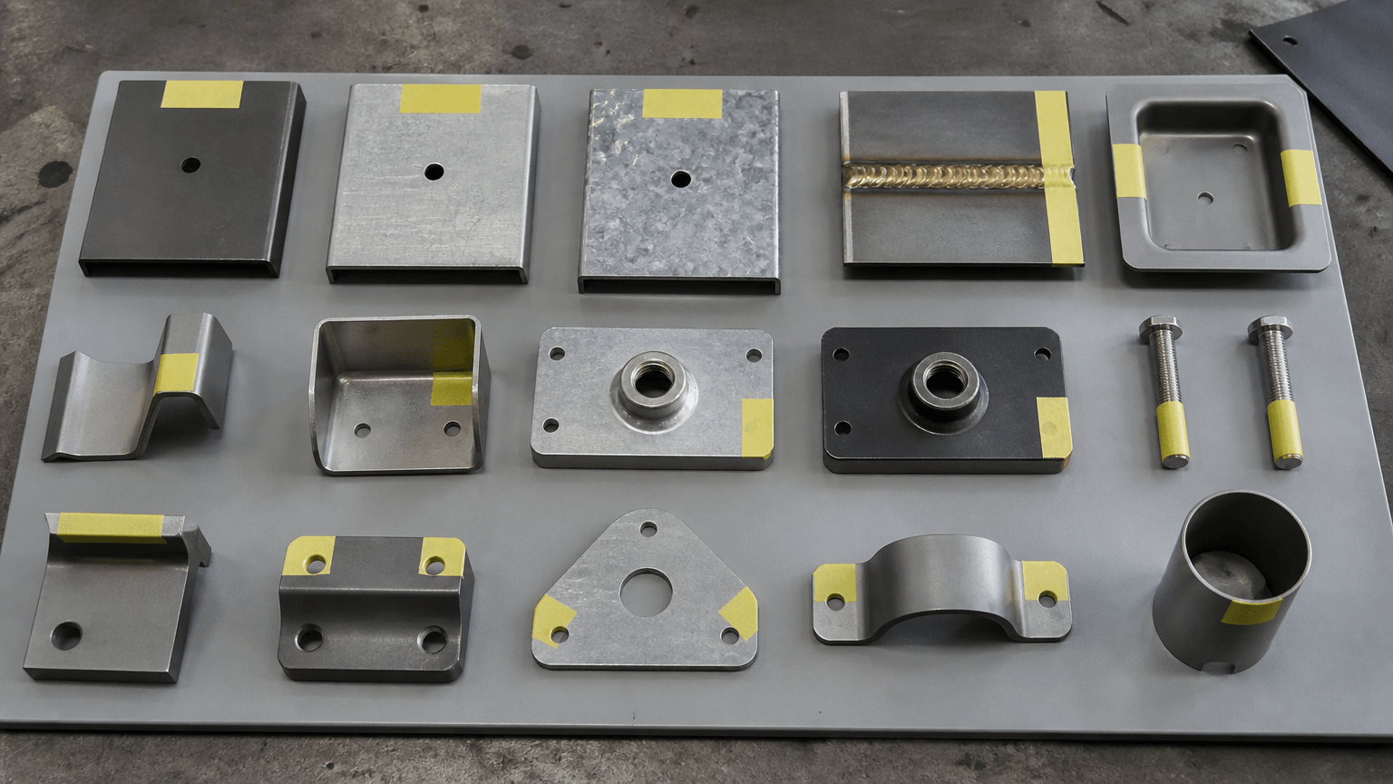
The same color powder can perform differently on two parts if their metals, surface conditions, welds, or geometries differ. These factors determine the preparation, masking, hanging, spray access, and process validation needed before an OEM buyer can expect a consistent production finish.
| Substrate or assembly | Process concern | Production control |
|---|---|---|
| Mild steel | Oil, rust, mill scale, grinding debris, and weld residue can affect adhesion and appearance. | Define the required surface condition and a compatible cleaning and pretreatment route, then protect the prepared surface from recontamination. |
| Aluminum | Oxide condition, alloy, handling marks, and pretreatment influence adhesion and visual uniformity. | Use an aluminum-compatible preparation route and validate the appearance on the actual alloy and part geometry. |
| Galvanized steel | The zinc surface, previous treatment, and gas release during heating can contribute to adhesion problems, pinholes, or blistering. | Use a compatible preparation and powder system, and evaluate outgassing risk on the actual galvanized surface. |
| Welded sheet-metal assembly | Spatter, residues, ground areas, heat-affected surfaces, joints, and cavities can create local variation. | Clean welds consistently and plan spray access, hanging, drainage, masking, and inspection around the complete assembly. |
Plan functional features before finishing
Holes, threads, hinges, deep recesses, internal corners, underside areas, and narrow channels can be difficult to coat evenly. Electrostatic effects may limit powder deposition in recessed areas or contribute to accumulation at edges, while rack contact points create intentional or unavoidable marks. Functional interfaces therefore need defined no-coat or masking requirements rather than an informal shop-floor assumption.
Sheet-metal cutting, bending, and forming create the component, while welding joins components and CNC machining may produce inserts, brackets, or mating parts. These are related but separate operations. If a machined part is installed in a sheet-metal assembly, the drawing or process plan should state whether it will be coated separately, masked at its fits, or installed after coating. Film build can affect threads, datums, press fits, seals, hinges, and other assembly interfaces, particularly when the complete assembly enters the oven.
What to include in an OEM finish specification
A useful finish specification converts a visual preference into a requirement that production and inspection teams can apply consistently. Without that detail, phrases such as powder paint, black finish, or smooth texture leave unresolved questions about masking, fit, appearance, and acceptance. Put the following information on the drawing, purchase order, approved sample record, or accompanying specification:
- Base material: State the metal, alloy or grade, thickness, surface condition, and whether the item is a single component or a welded assembly.
- Powder and appearance: Identify the required powder system or approved product where chemistry affects service, cure, or appearance. Provide an approved color reference or sample, along with gloss, texture, metallic content, or special-effect requirements when relevant.
- Coated and masked areas: Mark coated surfaces, no-coat zones, threads, holes, datums, grounding points, permitted rack-contact areas, and masking boundaries.
- Functional fit: Identify mating surfaces, press fits, sliding interfaces, hinges, seals, and assembly clearances that could be affected by film build.
- Film thickness: Set a target or acceptance range after considering the powder system, geometry, edge coverage, corrosion needs, and dimensional fit. There is no responsible universal value for every part.
- Inspection evidence: Define visual inspection conditions, defect limits, the color or gloss comparison method, sampling expectations, and any required film-thickness, adhesion, cure, or corrosion checks.
- Approval stage: For appearance-critical parts or difficult assemblies, define prototype or first-article approval before releasing the production batch.
The specification should give visible and functional requirements equal attention. A satisfactory color match does not by itself confirm coverage, adhesion, cure, or assembly fit.
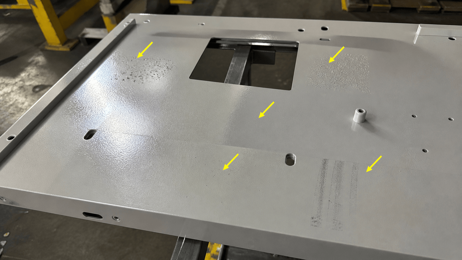
Inspection and powder-paint defect triage
Inspection should separate visual defects from functional or adhesion failures because the same part may pass one review and fail another. For example, the overall color may be acceptable even though a thread is blocked or a mating face has excessive film build. A rack mark may be permitted in an agreed non-visible area, but not where it affects fit or appears within a specified visible zone.
| Observed condition | Possible cause categories to investigate |
|---|---|
| Bare spots or incomplete coverage | Recessed geometry, poor gun access, weak grounding, displaced masking, low deposition, or rack contact. |
| Peeling or blistering | Oil, moisture, inadequate pretreatment, incompatible preparation, outgassing, cure problems, or handling damage. |
| Pinholes | Gas release, surface porosity, residue, contamination, or an unsuitable combination of film build and cure conditions. |
| Craters or fisheyes | Silicone, oil, dust, incompatible residue, powder contamination, or a surface-energy issue. |
| Orange peel or uneven flow | Film-build variation, powder condition, application settings, part temperature, or an unsuitable cure profile. |
| Runs or sags | Local over-application, edge accumulation, powder-retaining geometry, or flow outside the intended process window. |
| Color or gloss variation | Powder-lot differences, contamination, film-build changes, rack position, or inconsistent heating and cure. |
| Inconsistent cure | Differences in part temperature, heating time, load arrangement, oven zone, or powder-system requirements. |
| Visible rack marks | Unplanned contact, insufficient masking, or an agreed contact mark appearing in a visible or functional area. |
Defect triage: check preparation, application, cure, and handling in sequence
- Map the pattern. Record the lot, part location, orientation, rack position, weld area, recess, and whether the issue repeats across multiple parts.
- Check the substrate and pretreatment. Look for oil, rust, oxide, weld residue, moisture, grinding debris, and differences between affected and unaffected areas.
- Review the application stage. Check grounding, gun access, masking, edge build, recess coverage, powder condition, contamination, and measurements against the agreed film requirement.
- Verify the cure profile. Compare the powder supplier’s data with actual part-temperature measurements, heating time, time at temperature, load arrangement, and oven uniformity. Do not rely only on the controller display.
- Separate post-cure damage. Inspect handling, stacking, packaging, fastener contact, and transport marks before assigning the problem to preparation or curing.
Adhesion, film-thickness, cure, and corrosion tests should follow the project specification or customer requirement. Acceptance limits depend on the coating system, substrate, service environment, and agreed test method. Corrective-action records should identify whether the source was preparation, application, curing, handling, or packaging.
Choosing between powder coating and other finishes
Powder coating may suit a metal part when its substrate and assembly can tolerate the required preparation and thermal route, but the choice should not be made from appearance alone. During early design or RFQ review, compare the operating environment, thermal budget, part size and geometry, functional fit, batch volume, repair needs, and required inspection evidence.
| Finish route | Selection considerations | Process boundary |
|---|---|---|
| Powder coating | Uses dry electrostatic application followed by thermal fusion or cure on a compatible, prepared metal part. | Heat exposure, grounding, recess coverage, masking, film build, and post-cure repair must be planned. |
| Liquid paint | May suit a specified liquid-spray appearance, a different thermal budget, or a repair approach that better fits the project. | The liquid medium, drying or curing route, overspray, handling, and system-specific performance requirements need separate evaluation. |
| Anodizing | An electrochemical conversion process primarily associated with aluminum, modifying the surface rather than adding a conventional powder film. | Alloy response, color, dimensional effects, masking, and appearance depend on the aluminum and selected anodizing route. |
| Plating | Deposits a metal layer and may serve contact, wear, corrosion, soldering, or appearance objectives. | Its chemistry, dimensional effects, environmental controls, and inspection requirements differ from those of powder coating. |
Use the drawing, service conditions, functional interfaces, and inspection requirements to select the route. A review of available Surface Finishing options can help determine whether powder coating fits the part or whether another process should be specified before prototype approval.
Frequently asked questions about powder paint
These questions often arise while buyers are defining drawings, finish notes, prototype requirements, and inspection expectations for fabricated metal parts.
Is powder paint the same thing as powder coating?
Usually, in common purchasing language. Powder paint generally refers to the dry coating material, while powder coating is the more precise term for the complete process of preparing, applying, thermally fusing or curing, and inspecting that material on a part.
Do you need primer before powder paint?
Not automatically. The decision depends on the substrate, pretreatment, service environment, corrosion requirement, powder chemistry, and customer specification. A primer also changes film build, cure compatibility, masking needs, and assembly fit, so it should be selected as part of a validated coating system.
Can powder paint be used on aluminum or galvanized steel?
It can be used when the preparation route, powder system, and curing conditions suit the actual material. Aluminum alloy and oxide condition require attention, while galvanized steel may need compatible preparation and control of outgassing risk. The proposed route should be reviewed against the drawing, finish requirements, and actual substrate condition.
Why might a part peel, show bare spots, or have inconsistent color when the oven temperature appears correct?
The displayed oven setting does not confirm the actual part temperature or time at temperature. Other possible causes include contamination, pretreatment variation, weak grounding, difficult geometry, film-build differences, powder condition, rack position, or handling damage. Review the defect pattern by lot and part location, then compare the process record with the agreed drawing, finish specification, and inspection requirements before approving rework.