If an OEM drawing or RFQ says “solder weld,” clarify the term before choosing a process. In general industrial usage, the phrase is ambiguous: it may loosely mean soldering, be a mistaken reference to brazing or fusion welding, or identify a product or brand name. That ambiguity can change the quoted operation, joint design, consumables, inspection plan, and supplier scope.
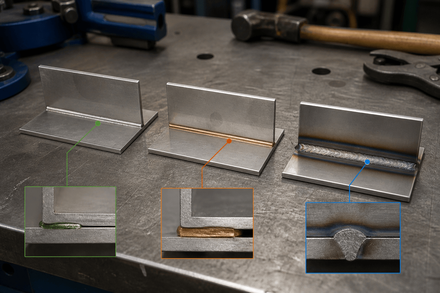
Quick answer: Soldering and brazing join solid base metals with a separate filler. In commonly used terminology, soldering uses filler in the lower-temperature range; brazing uses filler above that range but below the base-metal melting point. Fusion welding melts the base material locally, with or without added filler. These processes require different joint designs, materials, controls, and acceptance criteria.
For an OEM part, the distinction affects more than wording. It can change joint geometry, heat input, consumable selection, cleaning, appearance, inspection, and whether the selected supplier has the required process within its verified scope.
Interpreting “Solder Weld” on a Drawing
An OEM buyer may inherit the phrase from a legacy drawing, supplier note, or customer email. In general industrial use, solder weld may describe a soldered joint even though soldering does not fuse the base metals; the writer may instead mean brazing or welding.
Capitalization and surrounding product language may also indicate that “SolderWeld” is a brand or product reference rather than a generic process. If the wording comes from product literature, identify the manufacturer, exact product, technical data, intended materials, and application instructions. Do not convert a product name into a manufacturing callout without confirming the joining operation it requires.
On an OEM drawing, purchase order, or work instruction, the ambiguous phrase leaves practical questions unresolved. The manufacturer still needs to know whether the base metal is intended to melt, what function the joint must perform, whether filler or flux has already been specified, and how the completed joint will be inspected. Structural, pressure-containing, electrical, retention, and cosmetic joints should not be treated as equivalent.
Technical Differences Between Soldering, Brazing, and Welding
When a fabricator reviews a thin formed enclosure, conductive component, or other sheet-metal assembly, the joining category determines what happens at the joint. The principal distinction is the behavior of the base metal and filler. In commonly used terminology, the temperature boundary between soldering and brazing is a general classification, not proof that either process suits a particular material or service condition.
| Decision factor | Soldering | Brazing | Fusion welding |
|---|---|---|---|
| Base-metal behavior | The base metals remain solid. | The base metals remain below their melting point. | The adjoining base material melts locally and resolidifies. |
| Filler behavior | A lower-temperature filler wets prepared surfaces and fills the designed joint. | A separate filler melts and flows through the joint, often by capillary action. | Filler may be added, but the joint depends on fusion of the base material rather than filler flow alone. |
| Base-metal compatibility | Suitability depends on wetting, oxide behavior, filler and flux compatibility, and any dissimilar-metal combination. | Suitability depends on the base-metal combination, filler, flux or atmosphere, and heating limits. | Suitability depends on material weldability, thickness, fit-up, access, and the applicable welding procedure. |
| Heat input | Usually lower than brazing or welding, although thin sheet can still distort or discolor. | Can affect thin sections, coatings, dimensions, and adjacent components. | The heat-affected area and distortion depend on the process, material, thickness, fit-up, and weld length. |
| Joint design | Wetting area, overlap, access, and process-specific clearance can be important. | Fit and clearance are central to reliable filler flow. | Edge condition, fit-up, access, weld location, and required profile govern the joint. |
| Strength and function | May serve electrical, sealing, retention, or defined mechanical functions when properly specified. | May support different thermal or mechanical duties, but performance depends on the material, filler, and geometry. | Can create structural continuity, but performance still depends on joint design, defects, and base-metal behavior. |
| Surface preparation | Cleanliness, oxide control, and wetting are essential; flux may be required. | Oil, oxide, coating, and scale must be controlled for filler flow. | Contamination, coatings, oil, and scale must be addressed by the applicable welding procedure. |
| Appearance and cleaning | Filler lines or flux residue may affect finishing and electrical performance. | Fillets, discoloration, and residue may require cleaning or cosmetic review. | Bead profile, heat marks, spatter, distortion, or subsequent finishing may require control. |
This comparison describes general terminology rather than a project qualification, and it does not establish a universal strength ranking. Suitability depends on the approved material combination, joint geometry, service environment, manufacturing procedure, and acceptance plan.
Before Using “Solder Weld”: Match the Joint to the Requirement
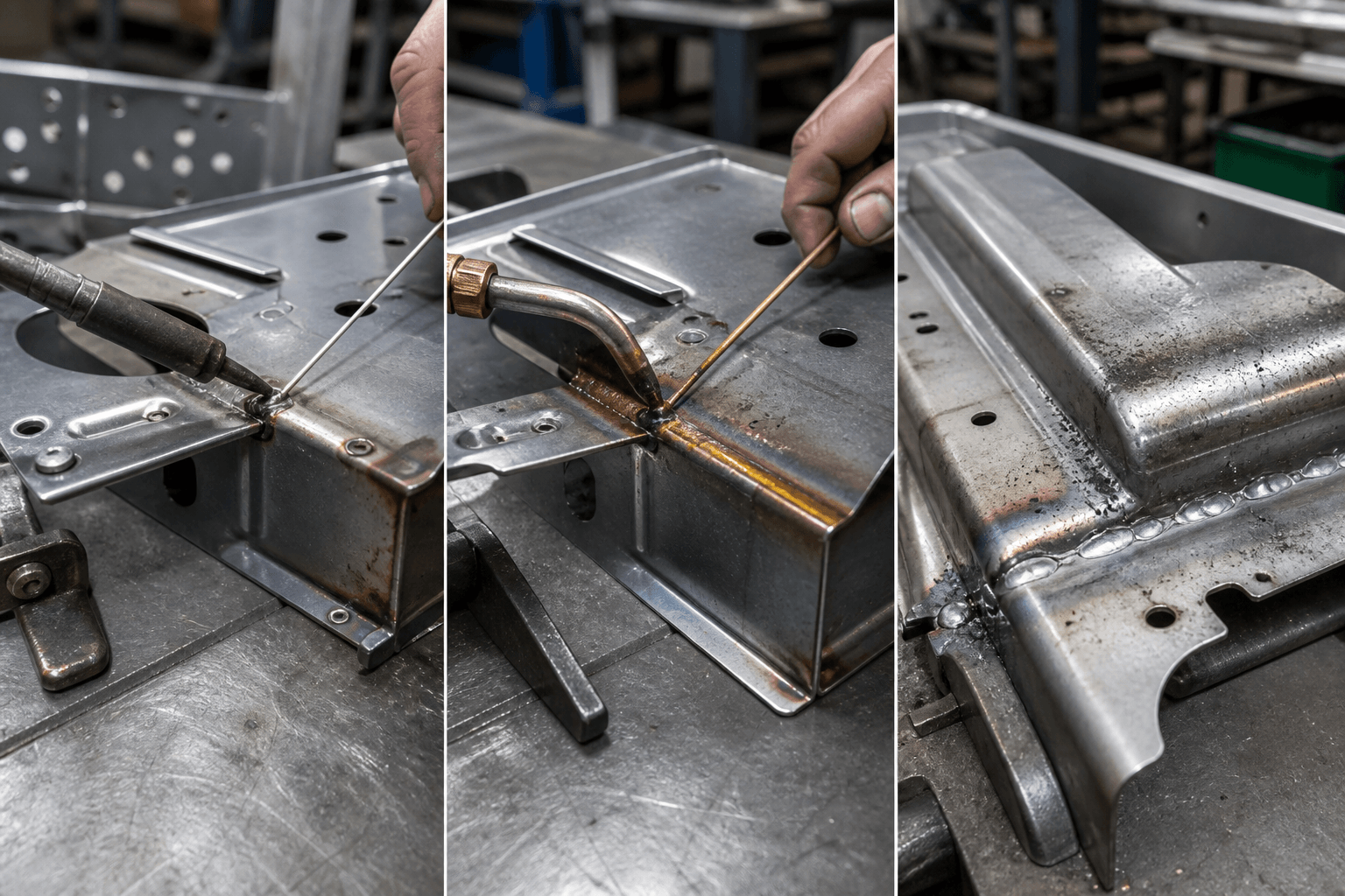
Material name alone does not determine the process. For a formed OEM assembly, sheet thickness, joint access, overlap or edge geometry, operating environment, surface condition, and required function must be considered together. The following matrix is a screening tool, not a process qualification.
| Part or requirement | Information to review | Process-selection consequence |
|---|---|---|
| Copper | Grade, thickness, conductivity requirement, heat-spreading behavior, surface condition, and any dissimilar metals. | Soldering, brazing, and welding may suit different designs. Filler compatibility, heat control, corrosion risk, and electrical function require separate review. See the relevant copper material considerations. |
| Aluminum | Alloy condition, oxide layer, thickness, coating or plating, and adjacent materials. | A process used for copper cannot be transferred automatically to aluminum. Surface preparation, filler or process compatibility, cleaning, and distortion controls must be verified. Review the applicable aluminum material considerations. |
| Steel or stainless steel | Grade, thickness, corrosion exposure, coating, heat-tint limits, and visible-surface requirements. | The route must address surface condition, joint duty, corrosion behavior, and post-join appearance. Stainless steel and coated steel require their own evaluation. |
| Coated or plated sheet | Whether the surface may be removed locally, must remain intact, or requires restoration after joining. | Coatings can interfere with wetting or fusion and can affect residue control, corrosion protection, fumes, and downstream finishing. |
| Thin sheet or restricted access | Joint overlap or edge geometry, process access, fixture access, permitted distortion, visible side, and dimensional tolerances. | Geometry may rule out a joining route before filler or equipment is selected. Required clearance must come from the verified process rather than a generic value. |
| Pressure or fluid service | Operating pressure and temperature, medium, cycling, corrosion exposure, and applicable equipment or local requirements. | Neither soldering nor brazing is automatically appropriate. The selected process and leak or pressure verification must match the specific application. |
| Electrical, structural, or cosmetic duty | Required conductivity, retention, load path, sealing function, visible appearance, and finish. | A visually neat joint does not demonstrate electrical, structural, or leak performance. Functional and cosmetic criteria should be specified separately. |
Information Needed to Define the Joint
A clear callout lets the supplier price the intended operation and lets engineering define acceptance before parts are made. Instead of writing only “solder weld,” identify the process or provide enough performance information for a documented technical recommendation:
- Joining category: State soldering, brazing, fusion welding, or an explicit request for process review. Include any customer-controlled specification or approved procedure.
- Part definition: Provide the current drawing revision, base-metal grade, thickness, temper where relevant, and coating or plating condition.
- Joint geometry: Show the cross-section, location, overlap or edge arrangement, dimensions and tolerances, access restrictions, visible side, and allowable distortion. Include a required clearance only when it has already been established by engineering documentation.
- Consumables: If filler and flux are already defined, identify them clearly along with documentation, cleaning, and residue-control requirements. Do not rely on the generic word solder.
- Service conditions: State operating temperature, pressure, fluid or chemical medium, electrical function, thermal cycling, and corrosion environment.
- Acceptance plan: Define visual criteria, dimensional checks, applicable strength or leak testing, residue limits, required records, and batch traceability. Name any special inspection rather than assuming it is available.
- Production context: Include quantity, prototype status, expected production volume, packaging constraints, and timing where these affect validation, fixtures, inspection planning, or supply arrangements.
Effects on Sheet-Metal Production Planning
Laser cutting and bending can create the sheet-metal geometry needed for edges, flanges, openings, and overlaps. They do not establish whether the components will be soldered, brazed, or welded. Joining is a separate production decision that must be checked against the formed geometry, tool access, fixtures, heat input, and downstream operations.
Finishing and assembly also remain distinct stages. Joining heat may affect coatings, visible surfaces, masking, dimensions, or nearby hardware, while flux residue may interfere with finishing or service performance. These consequences should be addressed in the route plan rather than left for inspection to resolve after production.
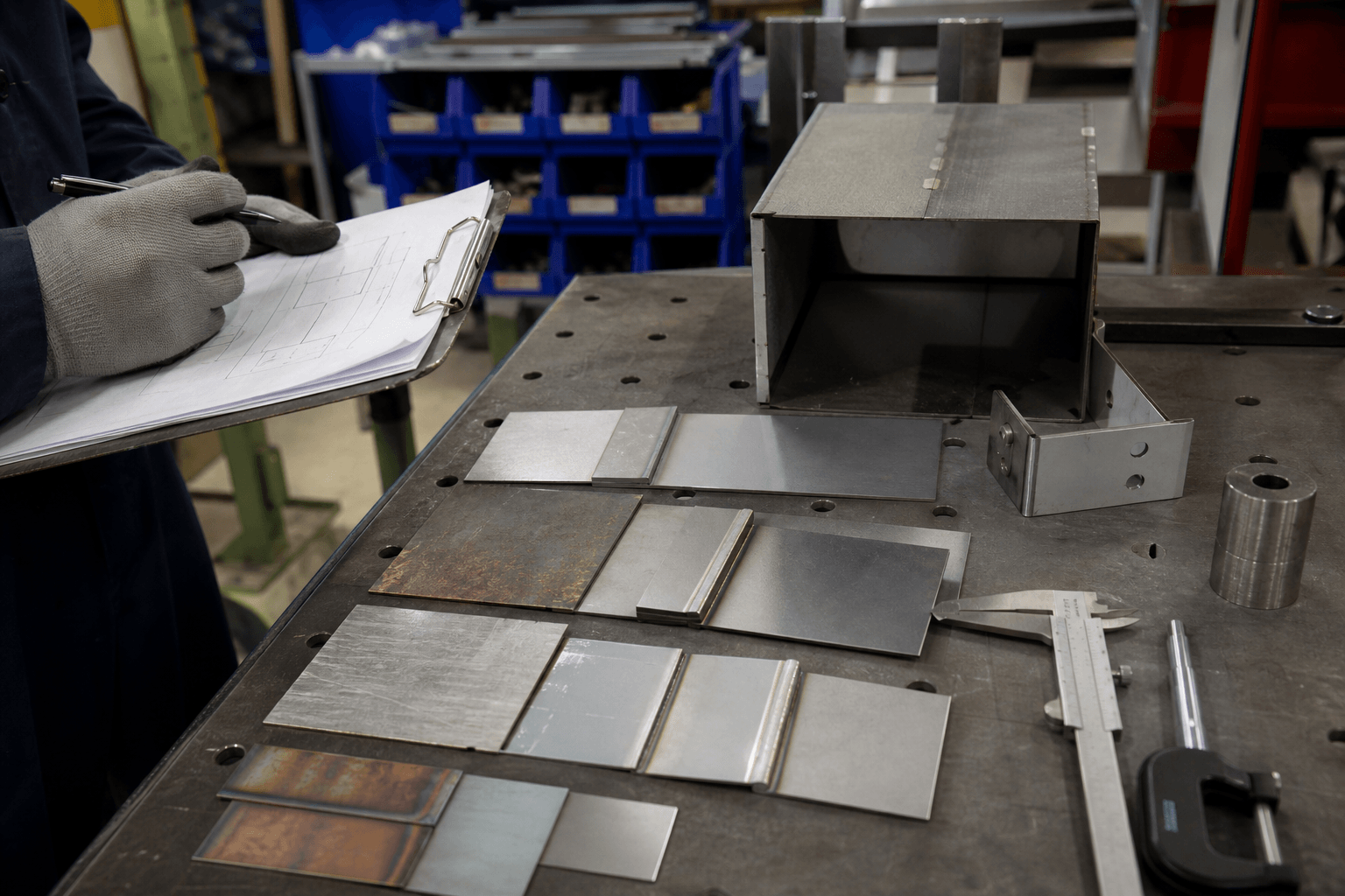
A practical handoff starts with drawing review and confirmation of the joint category. A representative prototype or sample can then be evaluated under the stated acceptance plan. Batch controls should identify approved base materials, filler and flux where applicable, surface-cleaning requirements, work instructions, visual criteria, dimensional checks, applicable strength or leak tests, residue controls, and traceability records.
If fusion welding is selected, compare the requirement with the supplier’s documented welding process scope. That review does not establish soldering or brazing capability. Inspection, documentation, and conformance requirements can be organized through a project-specific quality-control review.
For an RFQ or prototype review, send the marked joint, drawing revision, tolerances, finish, quantity, and service conditions before pricing.
The useful correction is straightforward: replace “solder weld” with a defined joining process or a documented request for technical review. This gives engineering, manufacturing, and inspection teams the same basis for evaluating the joint.
Frequently Asked Questions
These questions commonly arise when a legacy drawing or preliminary RFQ uses the phrase “solder weld.” The answers help separate terminology from the information needed to approve a production joint.
Is solder weld the same as welding?
No. “Solder weld” is ambiguous. Soldering joins solid base metals using a lower-temperature filler, whereas fusion welding melts the base material locally. Brazing also keeps the base metals solid but uses filler in the conventionally higher-temperature range.
Should an HVAC or fluid-carrying joint be soldered or brazed?
Neither process is automatically correct. Selection depends on the materials, pressure, medium or refrigerant, operating temperature, cycling, joint design, corrosion exposure, applicable equipment requirements, local requirements, and the specified leak or pressure verification. The applicable equipment, pressure, refrigerant, and local code requirements must be confirmed for the project.
Can copper, aluminum, stainless steel, and coated steel use the same joining approach?
No universal approach applies. These materials differ in oxide behavior, heat transfer, coating condition, filler compatibility, cleaning needs, corrosion risk, and response to joining heat. Each material and joint combination requires a documented review.
How should “solder weld” be clarified before quoting?
Confirm the process category, material grade and thickness, coating or plating, joint cross-section, access, dimensional tolerances, service environment, required function, cosmetic and finish limits, consumables if defined, inspection method, acceptance criteria, drawing revision, quantity, prototype needs, and traceability requirements. If the process remains open, provide the performance requirements and request a technical recommendation.