
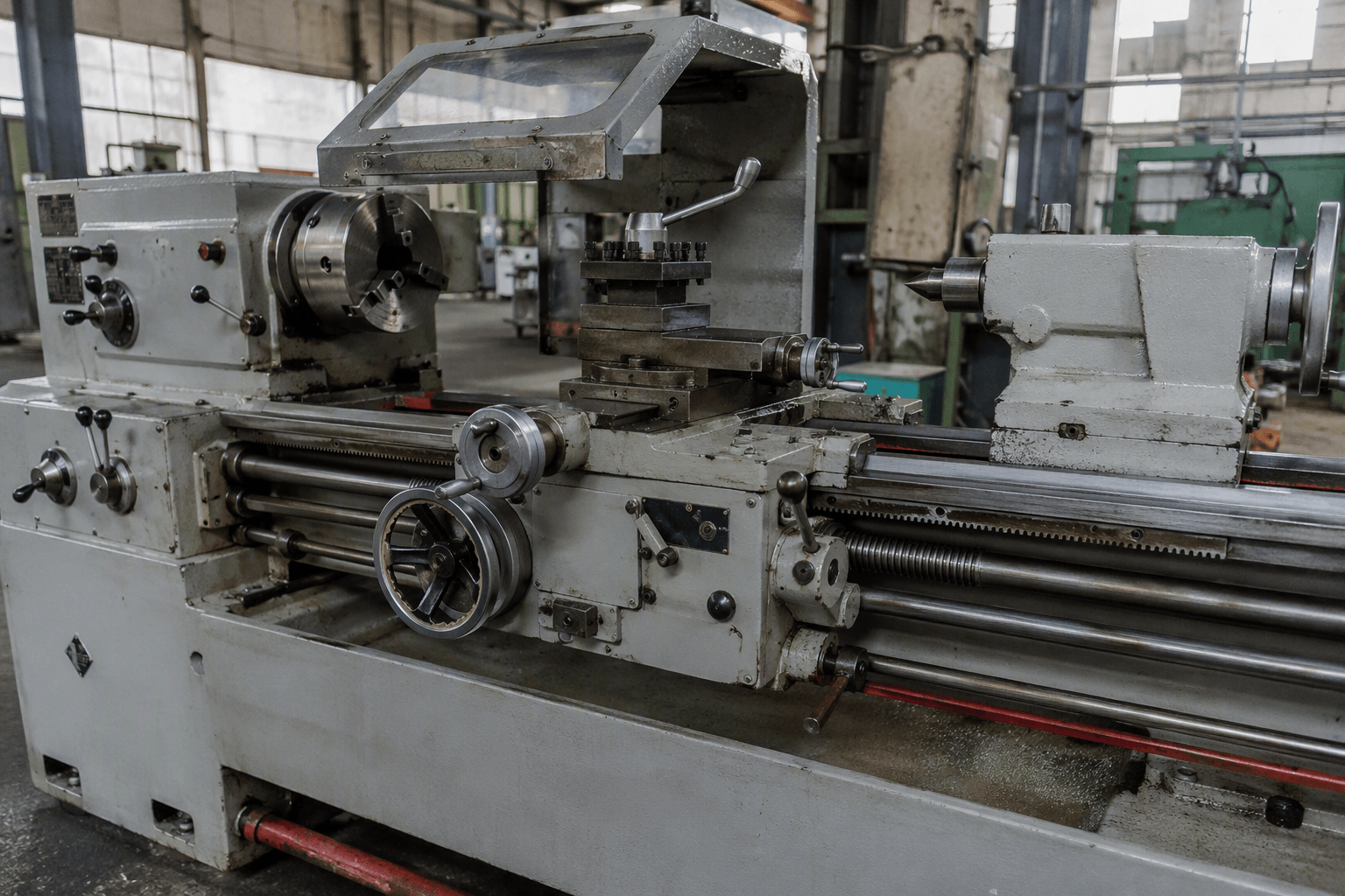
When a buyer compares a machine listing, checks a used lathe from photos, or reads a datasheet, a lathe parts description identifies the assemblies that support, rotate, position, and cut a workpiece. The phrase can also mean components made by turning, so define the category before interpreting specifications or preparing requirements.
Quick answer: A useful lathe parts description names each component, gives its location, states its function, and connects it with the relevant interface or specification. It separates structure, drive, workholding, support, carriage, tooling, feeds, guarding, and controls. Names and layouts vary among engine, turret, CNC, Swiss-type, and specialty lathes; the machine drawing or manufacturer datasheet remains the controlling reference.
What does “lathe parts description” mean?
If a used-lathe photo shows a chuck, carriage, or tailstock but the datasheet uses unfamiliar terms, the first task is to identify machine components rather than infer capacity. Here, parts of a lathe means the assemblies that make the machine operate.
Parts made on a lathe are different: they are turned workpieces described by outside diameters, bores, lengths, shoulders, grooves, tapers, threads, material, tolerances, surface requirements, and inspection points. That is a machined-part or turning description; the custom CNC machining overview is an adjacent resource for that interpretation.
Structural and drive components
For a layout review or a project involving a used engine lathe, trace the load and motion path before comparing numbers: the base supports the bed, the bed guides major assemblies, the headstock drives the spindle, and the carriage positions the tool.
| Component | Typical location | Function and detail to verify |
|---|---|---|
| Bed | Long horizontal structure | Supports and guides the headstock, carriage, and tailstock; confirm the guideway arrangement. |
| Base or legs | Below the bed | Supports the machine and transfers loads to the floor; the base may be integrated. |
| Headstock | At one end of the bed | Supports or contains the spindle, drive, and transmission; layout varies. |
| Spindle | Through the headstock | Rotates the workholding and workpiece; bore, nose, speed, and runout are separate terms. |
| Spindle nose | Front of the spindle | Mounting interface for a chuck, collet, faceplate, or other accessory. |
| Gearbox or drive | Headstock or drive area | Changes or transmits rotary drive; gears, belts, electronic control, or an integrated drive may be used. |
| Lead screw | Along the bed | Synchronizes carriage motion for thread cutting where fitted and configured. |
| Feed rod | Along the bed where fitted | Transmits powered routine feeds; it is not automatically interchangeable with the lead screw. |
| Guard or enclosure | Chuck, cutting zone, or drive area | Restricts access and may contain chips or coolant where fitted; arrangements vary. |
Headstock, spindle, spindle nose, and chuck are not interchangeable. The headstock is the larger support and drive assembly; the spindle is the rotating unit; the spindle nose is its front mounting interface; and the chuck is a removable workholding device. A chuck-size listing therefore does not by itself define spindle bore, spindle nose, or total workholding capacity.
Workholding and support at the spindle and tailstock
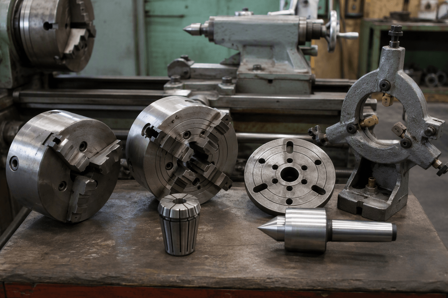
When a drawing involves a long, thin, irregular, or already machined workpiece, workholding and support terms matter as much as the nominal machine envelope. Selection depends on geometry, rigidity, length, access, and the required support points.
| Device | Basic principle | Details to verify |
|---|---|---|
| Three-jaw chuck | Jaws generally move together in a self-centering concept. | Profile, gripping range, interface, and jaw arrangement. |
| Four-jaw chuck | Jaws generally adjust independently. | Centering method, offset requirements, and non-round work. |
| Collet | Slotted sleeve grips a compatible profile. | System, size range, bar capacity, and interface. |
| Faceplate | Plate and fixtures hold unusual work. | Attachment, clearance, balance, and securing method. |
| Center | Supports work from a prepared center hole. | Live or dead center and center-hole suitability. |
| Tailstock | Movable support opposite the headstock; may carry a center or axial tool. | Quill or barrel travel, center interface, position, and offset if relevant. |
| Steady rest | Stationary support at a selected bed location. | Workpiece diameter, support location, and tool access. |
| Follower rest | Support that travels with the carriage or tool. | Support position, diameter range, and cutting access. |
For a suitable round or hexagonal profile, a three-jaw chuck may suit when a common self-centering arrangement is wanted. A four-jaw chuck, by contrast, allows independent adjustment for deliberate centering, offsetting, or non-round work. Collets suit a compatible profile within their system range, while a faceplate uses fixtures for work that does not suit a standard chuck. None of these descriptions establishes a guaranteed accuracy level; jaw condition, cleanliness, workpiece form, setup, and measurement method also matter.
Carriage, tooling, and feed mechanisms
If a listing names a carriage, compound, or apron but not the cutting tool, it is describing the tool-positioning system. This distinction matters when matching a holder, insert, or programmed tool path to the machine.
| Part | Location or movement | Function |
|---|---|---|
| Saddle | On the bed | Supports the cross slide and apron; travels longitudinally. |
| Cross slide | On the saddle | Moves the tool across the spindle axis for radial positioning. |
| Compound rest | Above the cross slide | Adds angular movement or fine manual adjustment. |
| Tool post | On the carriage or compound rest | Clamps a cutting tool or holder; it is not the cutting tool itself. |
| Apron | Front of the carriage | Contains many manual feed and engagement controls; layout is manufacturer-dependent. |
Longitudinal travel is parallel to the spindle axis. Cross travel is radial to that axis, while compound movement adds an angle or fine-adjustment direction. Where fitted, the lead screw synchronizes carriage motion with spindle rotation for thread cutting. The feed rod commonly transmits powered routine feeds, so it is not automatically a second name for the lead screw.
CNC lathes may use a turret, gang tooling, driven tools, or another automatic arrangement instead of a manual tool post and compound rest. A coolant delivery system belongs in the description only when fitted; then it directs fluid to the cutting zone.
Specification terms that complete the description
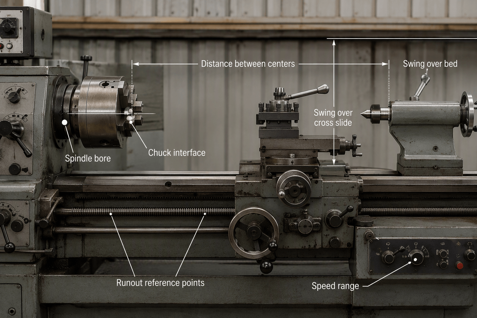
A datasheet can look complete while leaving the reference point or test condition unclear. Read each term as a defined machine measurement, interface, or control range rather than as a promise about a finished part.
| Term | General meaning | Definition or condition to verify |
|---|---|---|
| Swing over bed | Nominal diameter clearing the bed area. | Reference area and theoretical versus usable clearance. |
| Swing over cross slide | Nominal diameter clearing the cross-slide area. | Toolholder and cutting-path clearance. |
| Distance between centers | Nominal axial space between centers. | Center types, tailstock position, and setup clearance. |
| Travel | Available slide or axis movement. | Axis, usable travel, end clearance, and manual or CNC basis. |
| Spindle bore | Passage through the spindle. | Clear bore and through-work implications. |
| Spindle nose | Front spindle mounting interface. | Thread, taper, flange, registration, and compatibility. |
| Chuck size | Nominal size of a specified chuck. | Whether supplied or optional, plus jaw capacity and interface. |
| Spindle speed range | Available spindle rotation range. | Control, torque, material, tool, and operation limits. |
| Feed range | Manual settings or programmed feed values. | Units, axis, direction, and control basis. |
| Thread capability | Pitches, leads, or forms available in the configuration. | Units, gears or control, synchronization, and tooling. |
| Motor power | Rated drive power under stated conditions. | Continuous or peak basis, voltage, input or output, and torque. |
| Runout | Radial or axial deviation at a defined point. | Location, gauge method, thermal state, and workholding. |
| Positioning accuracy | Axis closeness to a commanded position. | Axis, test method, compensation, and environment. |
| Repeatability | Consistency of return to a position. | Approach direction and defined test conditions. |
Swing over bed is not the maximum practical cutting diameter. Tooling, workholding, chuck jaws, carriage clearance, tool access, rigidity, workpiece shape, and the operation all affect usable capacity. Check units, reference surfaces, included accessories, and measurement conditions. Runout, positioning accuracy, and repeatability should be tied to a measurement location, method, thermal state, and acceptance criterion; machine accuracy does not automatically equal finished-part accuracy. The Quality Control resource provides related context for verification language.
Manual and CNC terminology in context
When the same component appears in manual and CNC listings, the physical interface may be similar while the setup language changes. A buyer interpreting a retrofit, replacement, or production description should separate control terms from mechanical parts.
| Reading point | Manual lathe | CNC lathe |
|---|---|---|
| Control method | Handwheels, levers, and gearbox controls. | Programmed axes, offsets, and cycles. |
| Setup information | Tool height, carriage settings, workholding, and operator adjustments. | Coordinates, tool offsets, programs, and chucking details. |
| Tooling references | Tool post, holders, inserts, and compound-rest adjustment. | Turret stations, tool blocks, boring tools, or driven tools. |
| Axis terminology | Longitudinal and cross-slide movement. | X and Z axes, with additional axes depending on configuration. |
| Production context | Operator-controlled setup and movement. | Programs, cycles, tool capacity, offsets, and repeatability. |
CNC control changes how movement is commanded; it does not remove the need to define workholding, tool access, material, geometry, or inspection requirements.
Use this four-step terminology check:
- Identify the machine type. Is it an engine, turret, CNC, Swiss-type, or specialty lathe?
- Map each named component. Separate structure, drive, workholding, support, carriage, tooling, feed, guarding, and control terms.
- Confirm the specification definition. Check units, reference surfaces, included accessories, interfaces, and measurement conditions.
- Separate machine capability from part requirements. A turned component also needs material, dimensions, tolerances, threads, surface finish, quantity, and inspection requirements.
Lathe part-name decoder
This reference matrix connects common terms with the detail that should be confirmed in a drawing, listing, or manual.
| Term | Location | Function | Verify |
|---|---|---|---|
| Spindle | Headstock | Rotates workholding. | Bore, nose, speed, runout point. |
| Chuck | Spindle nose | Clamps workpiece. | Type, jaws, size, interface. |
| Tailstock | Opposite headstock | Supports work or carries an axial tool. | Quill, center, position. |
| Cross slide | On saddle | Provides radial tool motion. | Travel and clearance. |
| Compound rest | Above cross slide | Provides angular or fine adjustment. | Swivel and travel. |
| Tool post | Carriage | Holds a tool or holder. | Interface and indexing. |
| Apron | Front carriage | Contains many feed controls. | Manual layout and engagements. |
| Lead screw | Along bed | Synchronizes thread motion. | Pitch and engagement. |
| Feed rod | Along bed where fitted | Transmits routine powered feed. | Range and distinction from lead screw. |
Next step: send the right reference. For an existing lathe, share the model, datasheet, or a clear photo and identify the unclear component or specification. For a turned component, share the drawing or component photo, key dimensions, material, tolerances, surface finish, intended function, quantity, and whether the need is a prototype or repeat production. If the requirement is instead a sheet-metal part, enclosure, frame, or bracket, or a welded assembly, state that clearly and add the application, initial quantity, and assembly context where relevant. Keeping machining, sheet-metal fabrication, welding, finishing, assembly, and inspection as separate requirement categories helps route the technical discussion correctly before a quotation is pursued.
Where RFQ Assumptions Create Cost and Production Risk
Many sheet metal fabrication problems begin before production starts. If drawings, tolerances, finish expectations, material grades, or assembly requirements are unclear, suppliers may quote based on different assumptions. That can make prices difficult to compare and may lead to rework, cosmetic rejection, assembly misalignment, or production delays later.
For OEM buyers, the goal is not simply to request the lowest price. The goal is to make sure each supplier is quoting the same manufacturing reality. Before confirming an order, clarify which dimensions are fit-critical, which surfaces are cosmetic, whether prototypes must match batch-production conditions, and how finished parts will be inspected.
Frequently Asked Questions
These answers resolve the terminology issues most likely to affect a machine listing or a turning requirement.
Does “lathe parts” refer to parts of the machine or components manufactured by turning?
It can mean either. Machine parts include the bed, spindle, chuck, carriage, and tailstock. Turned components are workpieces defined by dimensions, material, tolerances, threads, finish, and inspection needs.
Are the headstock, spindle, and chuck the same part?
No. The headstock supports the drive and spindle, the spindle rotates, and the chuck is a removable workholding device mounted at the spindle nose.
What is the difference between a three-jaw chuck, four-jaw chuck, collet, and faceplate?
A three-jaw chuck generally moves jaws together, while a four-jaw chuck generally allows independent adjustment. A collet grips a compatible profile; a faceplate uses fixtures for unusual work.
Is swing over bed the same as the maximum workpiece diameter a lathe can practically machine?
No. It is a nominal clearance measurement. Practical capacity also depends on jaws, tooling, carriage clearance, access, rigidity, workpiece shape, and the operation.
How does a CNC lathe parts description differ from a manual lathe parts description?
A CNC description emphasizes programmed axes, offsets, control functions, tooling stations, and setup data. A manual description emphasizes handwheels, levers, gearbox settings, tool-post adjustment, and operator-controlled feeds.