
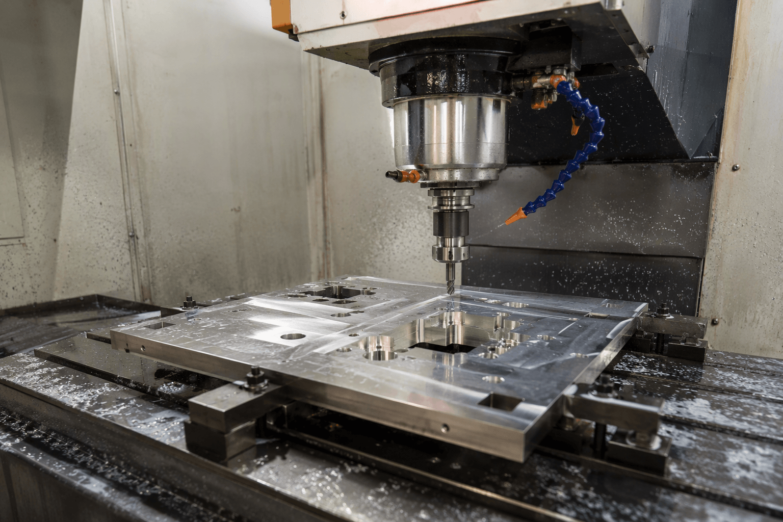
Computer numerical control, usually shortened to CNC, is used in equipment that follows programmed instructions to move tools, workpieces, or machine components. Common computer numerical control examples include CNC milling machines, lathes, routers, laser cutters, turret punches, press brakes, electrical discharge machines, and grinding machines.
For a buyer, the important distinction is not simply whether a supplier uses CNC equipment. The machine must also suit the part geometry, material, tolerance, finish, and production quantity. Understanding the main examples helps engineering and purchasing teams ask more useful questions before requesting a quotation.
What Is Computer Numerical Control?
Computer numerical control is a method of operating machinery through programmed commands. These commands control variables such as axis movement, tool position, feed rate, spindle speed, cutting sequence, and—in some equipment—tool changes or material handling.
A program may be written directly, generated from computer-aided manufacturing software, or produced through a machine-specific control interface. G-code is widely associated with CNC equipment, although the exact programming language, command set, and workflow vary by machine and controller.
CNC does not describe one manufacturing process. Instead, it describes how a machine is controlled. A mill removes material with rotating cutters, a lathe rotates the workpiece, and a laser cutter uses a focused beam, but all three can operate through numerical control.
Common Computer Numerical Control Examples
The following examples show how CNC technology appears across machining, sheet metal fabrication, and other manufacturing operations. Some create complete parts, while others perform one stage within a larger production route.
| CNC equipment | Primary action | Typical applications | Important project considerations |
|---|---|---|---|
| CNC milling machine | Moves a rotating cutting tool relative to a workpiece | Housings, brackets, pockets, slots, and precision surfaces | Tool access, setup count, corner radii, material, and tolerance |
| CNC lathe or turning center | Rotates the workpiece against a cutting tool | Shafts, bushings, pins, threads, and other rotational parts | Diameter-to-length ratio, concentricity, workholding, and secondary features |
| CNC router | Uses a rotating tool across a larger work area | Plastic panels, wood products, composites, and some nonferrous metal parts | Material rigidity, sheet support, edge quality, and tool selection |
| CNC laser cutter | Cuts sheet or plate with a focused laser beam | Flat profiles, holes, slots, panels, and sheet metal blanks | Material type, thickness, heat effects, kerf, and edge requirements |
| CNC plasma cutter | Uses a plasma arc to cut electrically conductive material | Steel plate, structural components, and larger fabricated parts | Plate thickness, cut tolerance, edge condition, and thermal distortion |
| CNC waterjet cutter | Uses a high-pressure water stream, often with abrasive | Metal, stone, glass, composites, and heat-sensitive materials | Cut speed, taper, edge condition, thickness, and material support |
| CNC turret punch | Punches sheet material with indexed tooling | Repeated holes, slots, louvers, knockouts, and sheet metal profiles | Available tooling, feature spacing, sheet utilization, and mark sensitivity |
| CNC press brake | Controls ram movement and back-gauge position during bending | Brackets, enclosures, channels, covers, and formed panels | Bend radius, flange length, tool access, bend sequence, and springback |
| CNC electrical discharge machine | Removes conductive material through controlled electrical discharges | Dies, molds, narrow slots, small radii, and hardened components | Electrical conductivity, electrode or wire access, speed, and surface requirements |
| CNC grinding machine | Uses an abrasive wheel under programmed motion | Precision diameters, flat surfaces, tooling, and finishing operations | Material hardness, stock allowance, heat control, and surface finish |
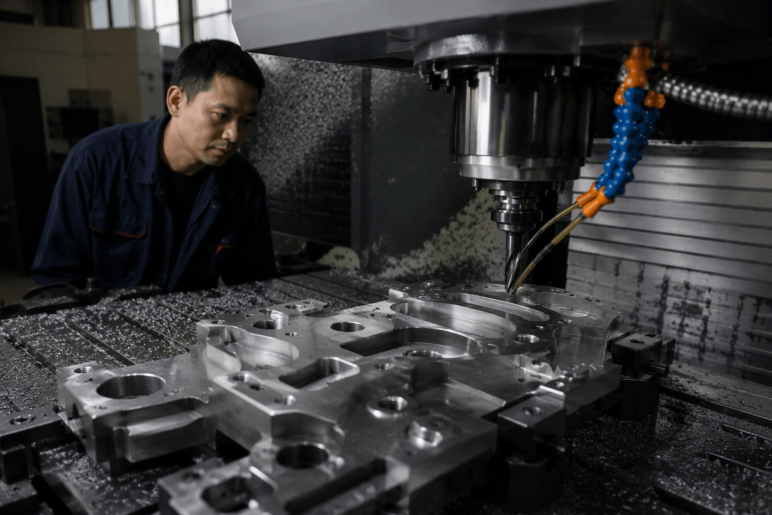
How a CNC Production Process Works
A typical CNC workflow begins with the part definition. The supplier reviews a drawing, three-dimensional model, or both to identify geometry, dimensions, tolerances, material specifications, surface requirements, and inspection notes. Missing or conflicting information should be clarified before programming because the drawing establishes what the finished part must meet.
Next, the programmer determines the manufacturing sequence. For machining, this may include workholding, cutting tools, toolpaths, spindle speeds, and feed rates. In sheet metal production, the sequence could involve nesting parts for laser cutting or punching, followed by deburring, bending, welding, and finishing.
The CNC program then converts the planned operations into instructions the controller can execute. Before routine production, the operator may simulate or verify the program, set tools and offsets, secure the material, and establish the machine reference points. The exact setup procedure depends on the equipment and the risk associated with the part.
Once the cycle starts, the machine repeats the programmed movements, but production is not entirely automatic. Operators still monitor tool condition, material behavior, workholding, chip removal, heat, and machine status. Tool wear, sheet variation, or an unstable setup can affect parts even when the program itself is unchanged.
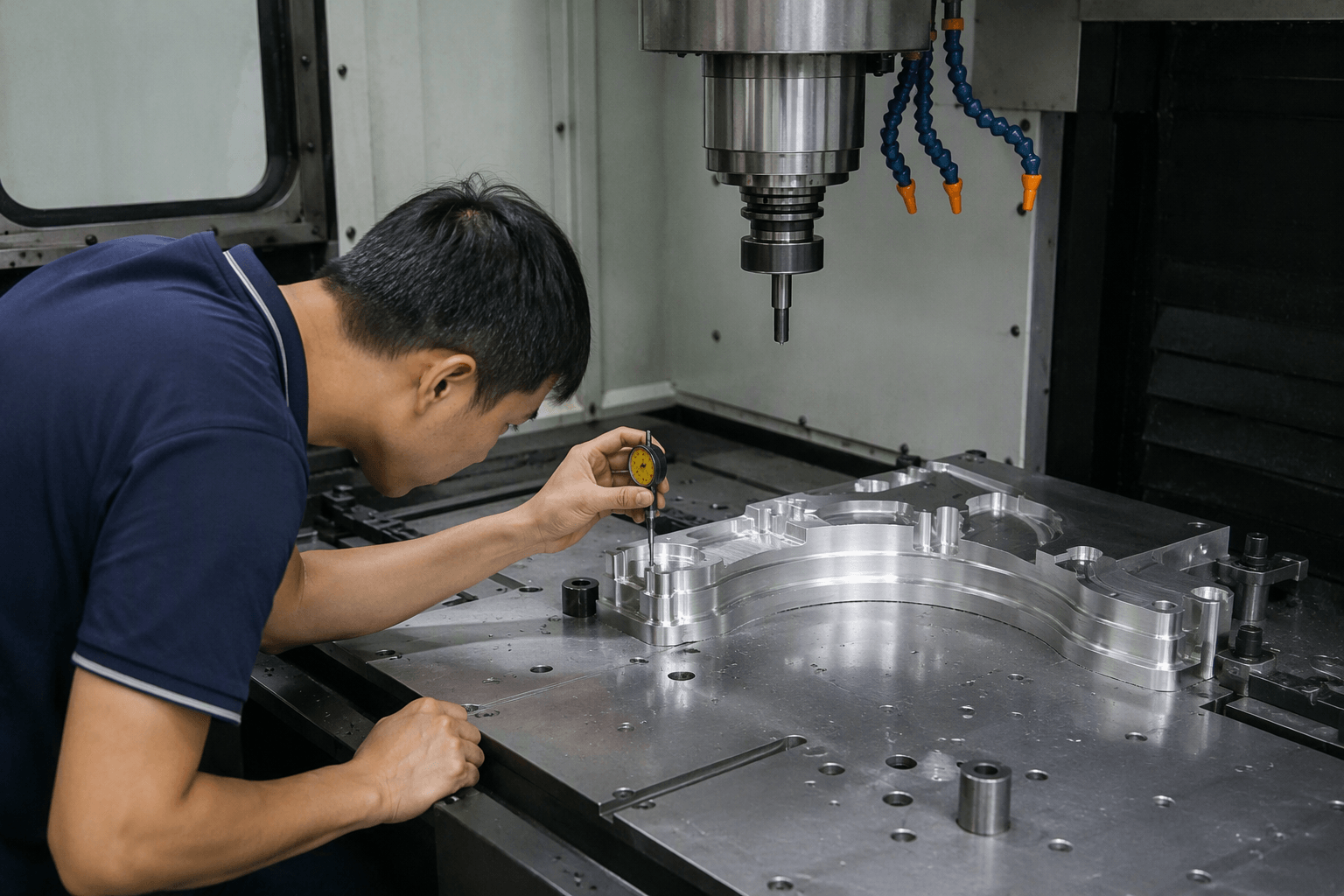
Inspection closes the loop between the digital instructions and the physical result. Depending on the specification, inspection may use calipers, micrometers, gauges, height measurement equipment, surface roughness instruments, or coordinate measuring machines. Findings can lead to offset adjustments, tool replacement, or process changes before the next batch continues.
Examples in Sheet Metal Fabrication
Sheet metal projects often pass through several CNC-controlled operations rather than one machine. A cabinet panel, for example, may begin as a flat blank cut by a CNC laser. It can then move to a CNC press brake for forming, followed by hardware insertion, welding, surface finishing, and assembly.
A ventilated enclosure may be better suited to a CNC turret punch when it contains many repeated holes, louvers, or standard punched forms. Laser cutting offers greater flexibility for varied profiles because it does not require a dedicated punch for every shape. The better choice depends on geometry, tooling availability, material, quantity, and the required condition of the cut features.
Forming introduces another set of decisions. The press brake program can control ram depth, bend sequence, and back-gauge position, but the finished angle also depends on the material, grain direction, bend radius, tooling, and springback. A flat drawing that ignores these factors may not produce the intended formed dimensions.
How to Match a CNC Process to a Real Project
Choosing a process begins with the feature that most strongly constrains production. Rotational symmetry generally points toward turning, while pockets and multi-face details commonly indicate milling. Flat sheet profiles may suit laser cutting, punching, plasma cutting, or waterjet cutting, with bending added when the part requires formed geometry.
Use the following questions as a practical review before sending an RFQ:
- What material and thickness are required? Material affects cutting behavior, tool wear, forming response, heat input, and available finishing methods.
- Which dimensions are functionally critical? Apply tight tolerances where assembly or performance requires them rather than treating every dimension the same.
- Can the tool reach each feature? Deep pockets, internal corners, narrow slots, and short bend flanges can restrict tool access.
- What edge and surface condition is acceptable? Burr limits, cut-edge appearance, machining marks, grain direction, and cosmetic surfaces should be identified.
- Is the quantity a prototype, bridge run, or recurring batch? Quantity influences setup strategy, nesting, tooling choices, and whether dedicated fixtures are practical.
- What happens after the CNC operation? Welding, hardware insertion, coating, plating, and assembly can change datum, masking, or tolerance requirements.
A complete RFQ does not need to prescribe every machine. In many cases, it is more useful to define the required result and allow the manufacturer to propose a suitable process. If a particular operation is mandatory for qualification or design reasons, that requirement should be stated clearly.
Review Your Part Before the RFQ Is Finalized
Unclear bend dimensions, incomplete finish notes, or tolerances that do not identify their functional purpose can delay quotation and create different assumptions among suppliers. This is especially relevant when a prototype must establish the production method for later quantities.
If you are preparing a custom sheet metal fabrication project, Yishang can review your drawing, material, quantity, tolerance, and finish requirements to clarify manufacturability and quotation assumptions. Send the project information through Yishang, including whether the request is for a prototype, a one-time batch, or recurring production.
What CNC Control Does Not Determine by Itself
CNC equipment can execute programmed movement consistently, but numerical control alone does not establish part quality. Results also depend on machine capability, tooling, fixtures, programming decisions, material condition, operator practices, and inspection controls.
The word “CNC” should therefore not be treated as a tolerance or finish specification. Two CNC processes can produce different edge conditions, radii, dimensional capabilities, and visible tool marks. Buyers should evaluate the proposed process against the drawing rather than relying on the machine label.
Where RFQ Assumptions Create Cost and Production Risk
Many sheet metal fabrication problems begin before production starts. If drawings, tolerances, finish expectations, material grades, or assembly requirements are unclear, suppliers may quote based on different assumptions. That can make prices difficult to compare and may lead to rework, cosmetic rejection, assembly misalignment, or production delays later.
For OEM buyers, the goal is not simply to request the lowest price. The goal is to make sure each supplier is quoting the same manufacturing reality. Before confirming an order, clarify which dimensions are fit-critical, which surfaces are cosmetic, whether prototypes must match batch-production conditions, and how finished parts will be inspected.
Frequently Asked Questions
What computer numerical control examples details should buyers define before requesting a quote?
Buyers should define the functional requirement, drawing notes, critical dimensions, material or process expectations, and any inspection points related to computer numerical control examples. This helps suppliers quote the same manufacturing scope instead of making different assumptions.
How can RFQ details affect cost, fit, or lead time?
RFQ details can change tooling, forming, welding, finishing, inspection, or rework requirements. If buyers do not clarify it early, two supplier quotes may look comparable while covering different production risks.
Why should drawing requirements be reviewed before prototype approval?
drawing requirements may look acceptable on a single sample but become harder to control during batch production. Buyers should confirm whether the prototype reflects the same process, finish, and inspection conditions expected for production.
What inspection points matter most for computer numerical control examples projects?
Important inspection points usually include fit-critical dimensions, holes or mating areas, cosmetic surfaces, finish build-up, welded or formed features, and any dimensions that affect downstream assembly. These points should appear in the RFQ or drawing notes.
How can buyers reduce prototype approval risk before batch production?
Buyers can reduce risk by clarifying drawings, locking key material and finish assumptions, defining inspection timing, approving a representative sample, and confirming which dimensions or surfaces require tighter process control.
How can Yishang help review computer numerical control examples requirements?
Yishang can review drawings, RFQ notes, material requirements, tolerance expectations, finish details, samples, and assembly needs to identify unclear assumptions before quoting or batch production.