
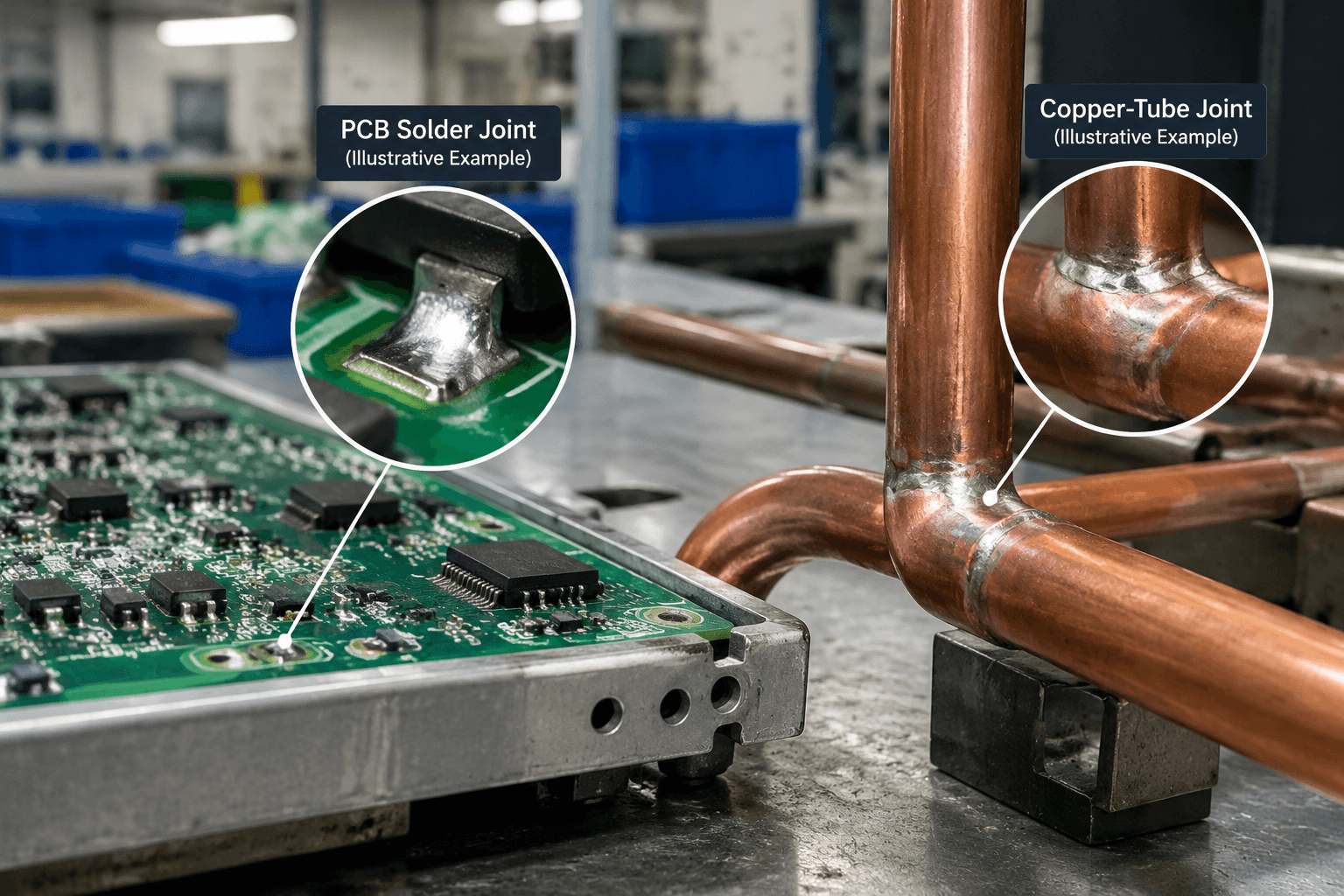
Solder is mainly used to create low-temperature mechanical or electrical joints, especially in electronics, electrical connections, selected copper-tube applications, and light-duty metal work. It is a lower-melting filler metal that flows into a prepared joint without melting the principal base materials. The correct choice depends on the base material, alloy, solder form, flux, service conditions, equipment, cleaning process, and compliance requirements.
For sourcing, terms such as lead-free, flux-core, rosin, and acid-core describe different properties. Buyers should define the alloy system, delivery form, flux chemistry or activity, residue classification, joint requirements, and supporting documentation before approving a solder product.
What is solder used for?
In manufacturing and repair work, solder joins compatible surfaces where controlled heat can create a mechanical connection without melting the primary base materials. In electronics, the joint also provides an electrical path. Solder selection does not by itself establish that a joint will withstand structural load, high temperature, pressure, fatigue, or severe environmental exposure.
- PCB and electronic connections: Solder joins component leads, wires, terminals, and printed circuit board pads. The joint normally needs to provide physical retention and a stable conductive path.
- Electrical terminals: Solder can connect conductors, lugs, contacts, and small terminals when current, temperature, strain relief, and mechanical loading have been validated.
- Copper tubing: Solder can fill the clearance between prepared copper tube and a fitting. Flux selection, joint preparation, residue removal, pressure conditions, and corrosion exposure all require review.
- Light-duty metal repairs: Selected thin-metal, cosmetic, model-making, and low-load joints may be soldered when the service environment is controlled and the substrate is compatible.
Base material, joint design, operating temperature, applied load, and environmental exposure determine whether solder is appropriate. The copper material overview provides background on copper, but copper selection alone does not establish that a soldered tube or component joint is suitable.
How does application change the soldering requirement?
A PCB, electrical terminal, copper tube, and light-duty repair differ in oxide behavior, heat sensitivity, joint loading, residue risk, and service environment. The same solder wire should not be selected simply because it worked on another metal or application.
PCBs and electronic assemblies
Electronic soldering generally requires controlled wetting and a flux system compatible with the components, board materials, and required residue condition. Excessive heat can damage pads, insulation, components, or nearby joints. A no-clean product still requires documentation and a review of whether its remaining residue or ionic contamination could affect corrosion or insulation performance.
Electrical terminals and wire connections
An electrical joint needs a conductive interface, but solder does not replace mechanical support where the connection experiences flexing, vibration, or pull-out forces. Terminal design, conductor preparation, plating, strain relief, and alloy selection must be considered together.
Copper tubes and fittings
Copper surfaces and their oxides require suitable cleaning and flux activation before solder can flow. A flux intended for copper-tube work may be more active than one intended for electronics, and its residue may require thorough removal. Pressure, temperature, fluid chemistry, access, and applicable installation requirements should be reviewed. Acid-core flux may be suitable for certain non-electronic metal applications only when the product instructions, substrate, cleaning process, and service environment support it; it is not a general recommendation for every copper-tube joint.
Light-duty metal and repair work
Thin copper, brass, steel, or coated metal can sometimes be soldered when the joint is not highly loaded and the environment is controlled. If the requirement involves a load-bearing enclosure, bracket, frame, or production assembly, compare soldering with fastening, brazing, welding, or another designed construction method.
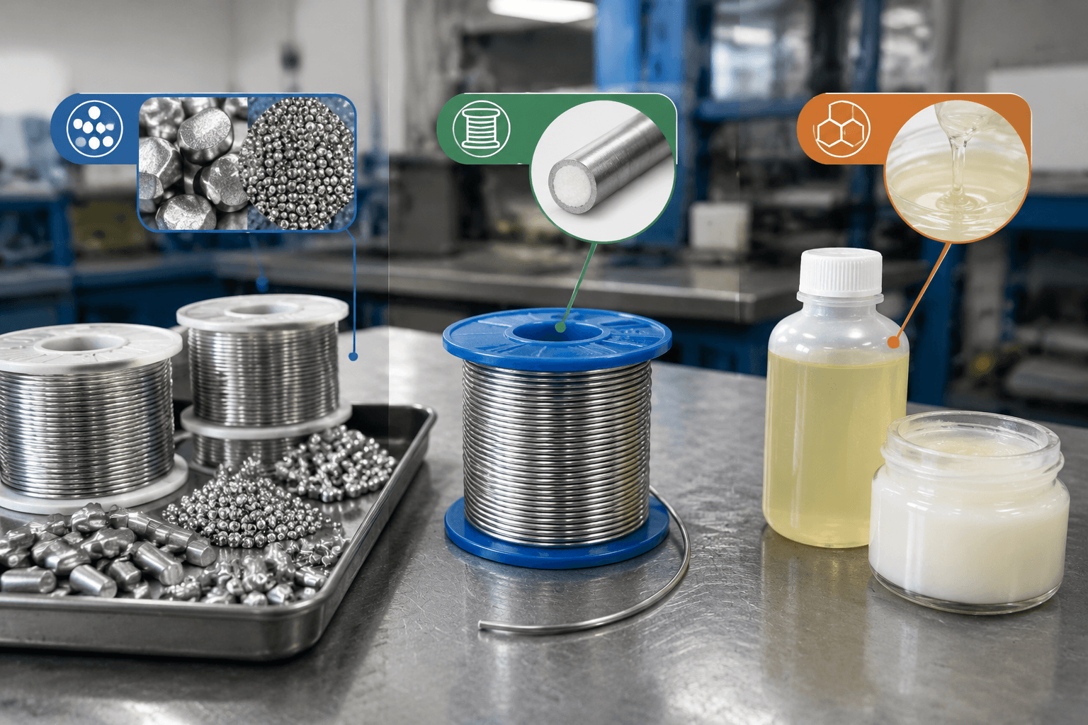
How should buyers separate alloy, solder form, and flux chemistry?
Supplier descriptions often combine terms from several specification dimensions. Separating them prevents a buyer from treating a wire construction, an alloy designation, a flux chemistry, and a residue classification as interchangeable.
| Specification dimension | Examples | What to confirm |
|---|---|---|
| Alloy system | Sn63/Pb37, SAC305, SnCu solder | Elemental composition, melting range, recommended working range, wetting behavior, regulatory status, and assembly compatibility. |
| Solder form or delivery method | Solid wire, flux-core wire, preform, paste | How solder and flux are delivered, wire diameter or dimensions, package format, dispensing method, and equipment compatibility. |
| Flux chemistry or activity | Rosin-based, organic, water-soluble, acid flux | Activity, substrate suitability, corrosion risk, required process controls, and compatibility with the selected alloy and assembly. |
| Residue or cleaning designation | No-clean, water-soluble residue, cleanable residue | Whether residue may remain, the required cleaning method, cleanliness criteria, and the effect on corrosion, insulation, coatings, or later processing. |
Flux-core describes a wire construction in which flux is contained inside the solder wire. Lead-free describes alloy composition. They are not alternatives in the same classification category: a product can be lead-free and flux-core, or lead-based and flux-core, depending on its specification.
As reference examples, a selected supplier datasheet commonly identifies Sn63/Pb37 as a tin-lead eutectic alloy with a melting point near 183°C, while SAC305 is a lead-free tin-silver-copper alloy with a published melting range commonly near 217–220°C. SnCu products vary by exact composition and designation. These values are not universal process settings. The current product datasheet must confirm composition, melting range, recommended working range, and flux compatibility for the specific material being purchased.
Lead-based solder commonly permits lower process temperatures and familiar wetting behavior, but lead restrictions, worker controls, environmental requirements, and destination-market rules may limit its use. Lead-free solder can require different thermal control and equipment capability because its process window may provide less margin between adequate wetting and thermal damage. Equipment compatibility should be confirmed during process qualification.
Rosin-based or no-clean flux may suit controlled electronic applications when its residue profile is acceptable. Acid flux can leave active residues that promote corrosion or affect insulation if they remain on an assembly. Do not use acid-core solder on electronics unless the product instructions, substrate, documented compatibility, and cleaning process specifically support that use. Do not infer RoHS or halogen-free status from a marketing name; request the supplier’s compliance declaration.
Silver-bearing alloys can affect material cost and availability, but the commercial effect also depends on the exact composition, wire diameter, packaging, flux construction, order volume, supply continuity, and process qualification. Treat these as procurement variables to confirm with supplier documentation rather than as universal cost claims.
What process conditions affect soldering results?
Before a solder specification is released for production, confirm that surface condition, joint design, heat transfer, flux activity, and residue handling support the intended application. Use the selected alloy and flux datasheets rather than a generic temperature promise.
- Prepare the surfaces: Remove oil, dirt, oxidation, coatings, and other contaminants using a method compatible with the base material and assembly.
- Review the joint design: Provide suitable contact and clearance for solder flow. Do not use a large solder fillet to compensate for poor mechanical engagement.
- Match the flux: Select activity and residue behavior for the substrate and application. More active flux is not automatically better because it can increase corrosion and cleaning requirements.
- Control heat: Follow the alloy and flux supplier’s recommended working range. Excessive heat can damage components, insulation, coatings, or thin metal, while insufficient heat can produce incomplete wetting.
- Inspect and manage residue: Review wetting, coverage, movement during cooling, and defined visual criteria. Determine whether residue is intended to remain, is water-soluble, is solvent-cleanable, or requires another control procedure.
Lead-free processing may need effective heat delivery and temperature measurement because its higher melting range can reduce the margin between adequate wetting and thermal damage. The usable process window depends on alloy, joint mass, substrate, component limits, and equipment configuration.
Solder-use selection matrix
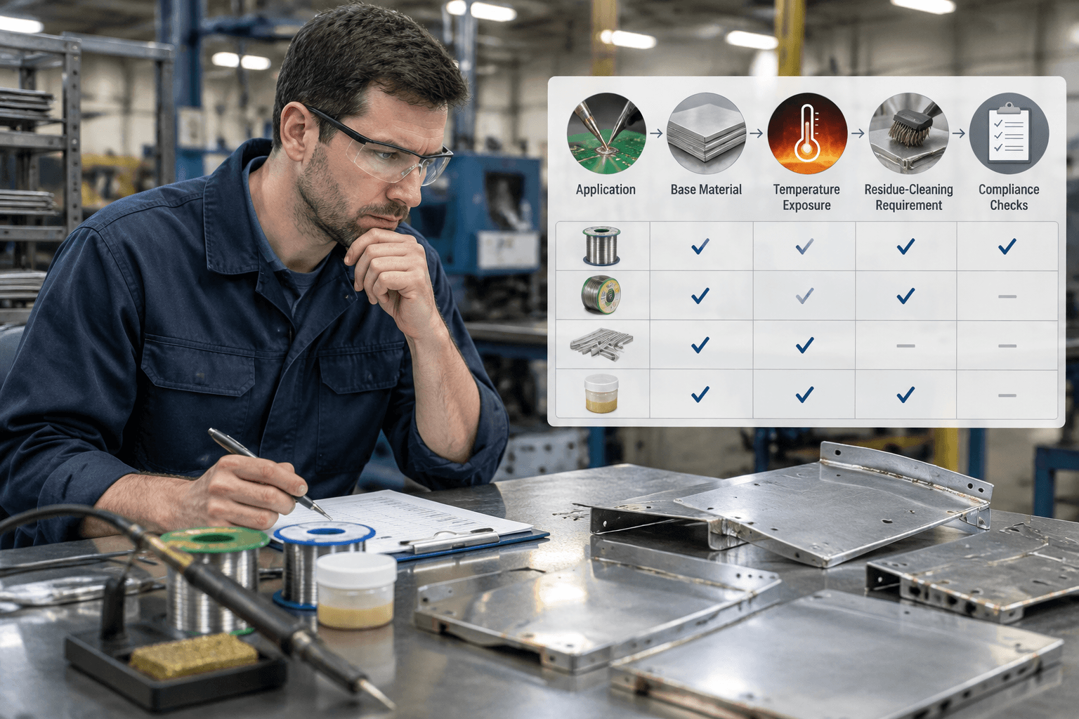
Use this matrix to narrow the supplier inquiry, then verify the final selection against current datasheets, the joint design, and the validation plan.
| Application | Typical base material | Alloy and flux direction | Equipment and cleaning focus | Primary risk |
|---|---|---|---|---|
| PCB assembly | PCB pads, component leads, copper conductors | Documented electronics alloy with compatible rosin-based, no-clean, or approved water-soluble flux | Controlled iron, selective, or reflow process; verify residue requirements | Thermal damage, poor wetting, corrosion, or insulation contamination |
| Electrical terminal | Copper wire, plated terminal, contact | Alloy and flux selected for conductivity, plating, and joint design | Control heat, provide strain relief, and inspect wetting | Fatigue, pull-out, high resistance, or damaged insulation |
| Copper tube | Copper tube and fitting | Tube-compatible alloy with flux whose activity and cleaning instructions match the application | Clean oxide and remove active residue according to the product instructions | Corrosion, incomplete fill, or application-specific pressure failure |
| Light-duty repair | Thin copper, brass, steel, or coated metal | Verify substrate compatibility; do not assume electronics flux is suitable | Control heat and surface preparation; assess adhesion and appearance | Insufficient strength, coating damage, or environmental degradation |
What should an OEM purchase specification include?
A purchase description such as lead-free solder or rosin-core wire is incomplete. The specification should define the material, delivery format, documentation, storage conditions, and traceability needed for consistent incoming lots.
- Alloy: Exact designation and elemental composition, including whether the material is lead-based or lead-free.
- Flux: Chemistry or classification, activity, core percentage where relevant, residue designation, and cleaning instructions.
- Form and dimensions: Solid wire, flux-core wire, preform, paste, or another format; wire diameter or preform dimensions; package and dispensing format.
- Documentation: Current technical datasheet, composition information, melting range, recommended working conditions, storage and shelf-life information, and safety data sheet.
- Compliance: Target-market requirements and supporting declarations. Do not infer RoHS or halogen-free status from a product name.
- Traceability and supply: Lot identification, manufacture or shelf-life information, storage conditions, change-notification expectations, approved alternatives, and requalification triggers.
- Incoming checks: Label and lot review, composition documentation, solderability or wetting verification where applicable, residue review, and batch records.
For technical approval, retain the current supplier datasheets for the selected Sn63/Pb37, SAC305, SnCu, and flux products, together with their safety and compliance documentation. These records should be the controlling reference for composition, melting range, working range, flux compatibility, residue handling, and storage. Compliance of the solder material is not the same as compliance of the finished product. A documented quality plan, such as the considerations in general quality control planning, should separate incoming-material verification from final product inspection.
When is solder the wrong joining method?
Compare another process when the joint must carry substantial structural load, tolerate repeated fatigue, operate near or above the solder’s validated service range, contain pressure, or withstand severe vibration, moisture, chemicals, or corrosion. Heating may also be unsuitable where nearby parts are heat-sensitive.
- Brazing: A higher-temperature filler process may suit some joints that need greater heat resistance or a different mechanical design. Material compatibility, clearance, heating, and validation remain necessary.
- Welding: Welding generally joins materials by locally melting the base materials, with or without filler. It may be considered for load-bearing frames, brackets, or sheet metal assemblies, with its own heat-affected-zone, distortion, inspection, and design considerations.
- Mechanical fastening: Screws, rivets, clips, or inserts may be preferable where service access, disassembly, heat avoidance, or predictable clamping is important.
- Fabricated construction: If the requirement calls for formed sheet metal, machined features, or welded subassemblies, define that manufacturing route separately instead of treating solder as a substitute for the required component design.
A soldered electronic connection and a load-bearing sheet metal frame have fundamentally different joining requirements. Neither solder nor an alternative process is universally superior; selection should follow the materials, loads, service environment, access, production volume, and validation plan. Compare a metal-component requirement with a custom sheet metal fabrication route where appropriate.
Request an application-fit review: Contact Yishang with a part drawing, joint sketch, or clear photographs; base-metal types and thicknesses; whether the joint is electrical, cosmetic, pressure-related, or structural; operating temperature, load, corrosion, and cleaning conditions; target-market compliance requirements; and expected production volume. The discussion can help determine whether custom sheet metal fabrication, welded construction, or another metal-component route is more appropriate than assuming soldering is the right solution. This is not a soldering-service request.
Where RFQ Assumptions Create Cost and Production Risk
Many sheet metal fabrication problems begin before production starts. If drawings, tolerances, finish expectations, material grades, or assembly requirements are unclear, suppliers may quote based on different assumptions. That can make prices difficult to compare and may lead to rework, cosmetic rejection, assembly misalignment, or production delays later.
For OEM buyers, the goal is not simply to request the lowest price. The goal is to make sure each supplier is quoting the same manufacturing reality. Before confirming an order, clarify which dimensions are fit-critical, which surfaces are cosmetic, whether prototypes must match batch-production conditions, and how finished parts will be inspected.
Frequently Asked Questions
What solder uses details should buyers define before requesting a quote?
Buyers should define the functional requirement, drawing notes, critical dimensions, material or process expectations, and any inspection points related to solder uses. This helps suppliers quote the same manufacturing scope instead of making different assumptions.
How can RFQ details affect cost, fit, or lead time?
RFQ details can change tooling, forming, welding, finishing, inspection, or rework requirements. If buyers do not clarify it early, two supplier quotes may look comparable while covering different production risks.
Why should drawing requirements be reviewed before prototype approval?
drawing requirements may look acceptable on a single sample but become harder to control during batch production. Buyers should confirm whether the prototype reflects the same process, finish, and inspection conditions expected for production.
What inspection points matter most for solder uses projects?
Important inspection points usually include fit-critical dimensions, holes or mating areas, cosmetic surfaces, finish build-up, welded or formed features, and any dimensions that affect downstream assembly. These points should appear in the RFQ or drawing notes.
How can buyers reduce prototype approval risk before batch production?
Buyers can reduce risk by clarifying drawings, locking key material and finish assumptions, defining inspection timing, approving a representative sample, and confirming which dimensions or surfaces require tighter process control.
How can Yishang help review solder uses requirements?
Yishang can review drawings, RFQ notes, material requirements, tolerance expectations, finish details, samples, and assembly needs to identify unclear assumptions before quoting or batch production.