
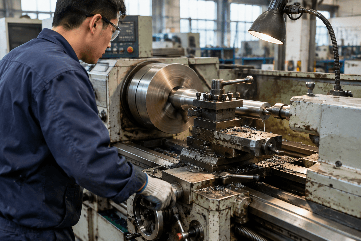
Operating a lathe machine means securing a workpiece, rotating it about a spindle axis, and moving a cutting tool against it to remove controlled amounts of material. Depending on the setup, the process can produce external diameters, faces, shoulders, grooves, tapers, threads, holes, and internal bores.
The operator’s work involves more than starting the spindle. It includes interpreting the drawing, choosing workholding and tooling, setting cutting conditions, checking clearances, controlling the cut, and inspecting the result. A manual lathe relies mainly on handwheels and mechanical feeds, while a CNC lathe uses programmed coordinates and tool offsets. Both require sound alignment, adequate rigidity, and controlled cutting.
Lathe machine parts and how they work together
In a conventional horizontal lathe, the workpiece rotates while the cutting tool generally travels along or across the spindle axis. The main lathe machine parts form one mechanical system:
- Headstock and spindle: The headstock supports the spindle and drive system. The spindle provides the rotation required for turning.
- Chuck or collet: This holds the workpiece on the spindle. A chuck suits a wide range of shapes, while a collet is often selected for suitable bar or small-part work.
- Bed and ways: The bed supports the machine and provides guided paths for the carriage and tailstock. Its rigidity and alignment affect cutting stability.
- Carriage, cross-slide, and tool post: These components position the tool. Longitudinal movement follows the workpiece axis, while cross movement controls radial position for turning and facing.
- Tailstock: The tailstock supports the free end of a long workpiece with a center. It can also hold a drill chuck or another axial tool.
The relationship between these parts affects runout, coaxiality, taper, vibration, and surface finish. A powerful spindle cannot compensate for poor workholding, excessive tool overhang, misaligned centers, or a weak setup.
Operating a lathe machine: setup and cutting sequence
- Review the drawing and material. Identify the datum, stock size, finished diameters and lengths, shoulders, threads, holes, grooves, tolerances, and required surface finish. Material selection affects tooling, cutting speed, chip control, and coolant decisions.
- Inspect and prepare the machine. Check lubrication, guards, tool condition, chuck or collet condition, emergency controls, and the work area in accordance with the machine manufacturer’s instructions and site procedures. Never leave a chuck key in the chuck, and keep loose clothing, tools, and other objects away from rotating components.
- Select the workholding method. Choose a three-jaw or four-jaw chuck, collet, faceplate, or centers according to the part geometry and accuracy requirements. Confirm sufficient jaw engagement and avoid unsupported overhang. Long or slender work may require a tailstock center or other support.
- Set the cutting tool. Install a suitable turning, facing, grooving, threading, boring, or parting tool. Set the cutting edge at the correct height where applicable and minimize unnecessary tool extension. On a CNC lathe, confirm the tool station, geometry and wear offsets, and work coordinate data.
- Set cutting conditions. Select spindle speed from the workpiece diameter, material, and tooling recommendations. At the same surface speed, a larger diameter requires a lower spindle speed. Feed and depth of cut depend on the roughing or finishing stage, tool geometry, material, machine rigidity, workholding, and required finish.
- Prove the movement. With the spindle stopped, move a manual-lathe tool through the intended path and check clearance. On a CNC machine, use graphics, dry-run, single-block, or equivalent verification functions where available and appropriate. Check clearance around the chuck, jaws, shoulders, tailstock, and boring bar.
- Machine in a planned sequence. A typical sequence may include facing, rough turning, shoulder or groove work, drilling or boring, threading, finish turning, and parting off. The actual order depends on the datums, support, tool access, and feature relationships. Leave suitable material for finishing cuts instead of trying to achieve every dimension during roughing.
- Inspect and adjust. Measure the first part and check critical features during production with suitable measuring equipment. Review diameters, lengths, holes, threads, runout, and surface finish as required by the drawing. If a dimension trends away from the requirement, correct the tool offset or process condition before more parts are produced. Clear chips with an appropriate brush or hook and never use your hands near moving components.
Illustrative setup examples: A long shaft may be turned between centers for additional support, while a short flange may be machined in a chuck with facing and boring completed in one setup. The drawing and the required datum relationships determine the suitable approach.
Machine structure, rigidity, and dimensional control
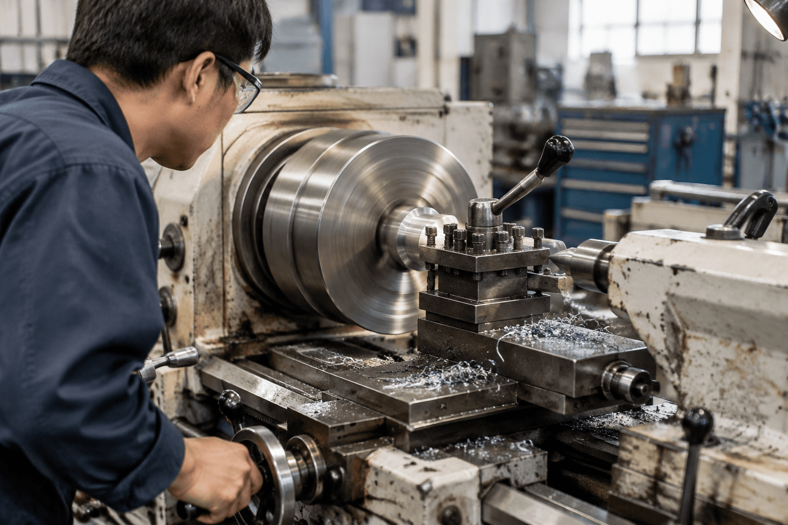
Accuracy does not come from one machine specification. It results from the spindle, workholding, guideways, tool system, cutting conditions, thermal state, and inspection method working together.
- Spindle and workholding: Spindle bearing condition, chuck or collet quality, jaw contact, and clamping force influence runout and repeatability. A workpiece that shifts during cutting can lose its relationship with the original datum.
- Bed, ways, and carriage: The bed must resist cutting forces while the ways guide the carriage. Wear, contamination, backlash, or insufficient rigidity can contribute to taper, chatter, and inconsistent dimensions.
- Tool system: Tool-holder rigidity, insert condition, cutting-edge height, and tool overhang affect deflection and vibration. Excessive extension is especially problematic when boring or machining a slender feature.
- Tailstock and centers: Tailstock alignment matters when supporting long parts or machining between centers. Excessive pressure can deform a part, while insufficient support can allow vibration.
- Leadscrew and feed rod: On a conventional lathe, the leadscrew is mainly used to synchronize tool movement with spindle rotation for thread pitch. The feed rod normally provides ordinary powered longitudinal or cross feed. These functions are not interchangeable. Many CNC machines use electronic synchronization and servo motion rather than the manual leadscrew method.
Heat also matters during longer production runs. Spindle and workpiece temperature can change dimensions, so a stable process may require warm-up practice, consistent cutting conditions, and inspection at suitable intervals.
Choose a lathe for the part and production pattern
Manual lathe, CNC lathe, and turning center are useful practical categories, but they are not a complete universal classification. The suitable choice depends on part geometry, quantity, tolerances, material, and the amount of automation or secondary machining required.
| Job condition | Possible machine fit | Important points to verify |
|---|---|---|
| One-off parts, repairs, prototypes, or frequently changing work | Manual or engine lathe | Operator skill, work envelope, gearbox or feed range, tooling, and workholding flexibility |
| Repeating batches with several turning features | CNC lathe | Axis travel, spindle bore, chuck capacity, turret stations, control functions, offsets, and chip management |
| Turned parts requiring driven tools or additional cross features | Turning center configured for the required operations | Live tooling, available axes, tool capacity, workholding, and whether the required operation is supported |
For any category, compare maximum swing, usable turning diameter, turning length, spindle through-bore, chuck or collet capacity, power and torque, speed range, feed range, and tailstock or steady-rest options. Maximum swing describes clearance over the bed; it does not automatically represent the practical diameter for every operation because the cross-slide, toolholder, workholding, and other components also limit access.
For harder materials or interrupted cuts, rigidity and torque may matter more than maximum speed. For small-diameter parts, tool access, collet capability, speed control, and chip evacuation may matter more. If the part combines turning with milling-type cross holes, slots, or flats, confirm whether a suitably equipped turning center is appropriate or whether a separate operation is required.
From drawing to a workable lathe plan
Before choosing a machine or comparing manufacturing options, convert the part drawing into a short process and capacity review:
- Define the geometry: List the largest diameter, finished length, hole and thread features, slender sections, shoulders, grooves, and any cross features.
- Define the production demand: State the quantity, repeat frequency, and whether future volume may change. This helps distinguish manual flexibility from CNC repeatability or automation.
- Identify critical requirements: Mark the dimensions, concentricity relationships, thread details, and surface finish that affect function. Do not treat every dimension as equally difficult.
- Review the setup: Consider chuck access, jaw marks, tool clearance, tailstock support, multiple setups, part transfer, and the need for a secondary operation.
- Plan inspection: Decide how critical features will be measured and when first-part or in-process checks are needed. The inspection method should relate to the drawing requirements rather than to the machine label.
Turning on a lathe removes material from a rotating workpiece. A lathe can drill or bore along the spindle axis, but a cross-hole, slot, or flat may require live tooling on a turning center or a separate milling operation. If a turned shaft, pin, or bushing interfaces with a sheet-metal bracket, identify the turned component and the bracket as separate process scopes in the drawing, quotation, and inspection plan. This keeps turning, sheet-metal fabrication, and assembly requirements from being treated as one unspecified operation.
If you are evaluating a custom turned component or an OEM assembly, you can share a drawing, material, quantity, tolerance, and finish through Yishang. An application review can help clarify manufacturability and quotation assumptions for the requested scope before production planning.
Frequently Asked Questions
What is the correct order for operating a lathe machine?
Start by reviewing the drawing and material, then inspect the machine, select workholding, set the tool, establish speed and feed, verify tool clearance, machine the planned sequence, and inspect the result. The exact order and safety controls depend on the machine, part, and site procedure.
How does operating a manual lathe differ from operating a CNC lathe?
On a manual lathe, the operator directly controls handwheels, gears, and mechanical feeds. A CNC lathe follows a program and uses tool offsets and coordinated servo motion. Both still require correct workholding, tool setup, clearance checks, cutting conditions, and inspection.
How does workholding affect turning accuracy?
Chuck or collet condition, jaw contact, clamping force, runout, and unsupported overhang affect how securely the part maintains its datum. Poor support can cause movement, deflection, taper, vibration, or inconsistent dimensions even when the lathe operator uses suitable cutting conditions.
When should a turning center be considered instead of a basic CNC lathe?
A turning center may be appropriate when the part combines turning with supported cross features, such as holes, slots, or flats, and the machine has the required live tooling, axes, and workholding. If those functions are unavailable or unnecessary, a basic CNC lathe or a separate operation may be more suitable.