
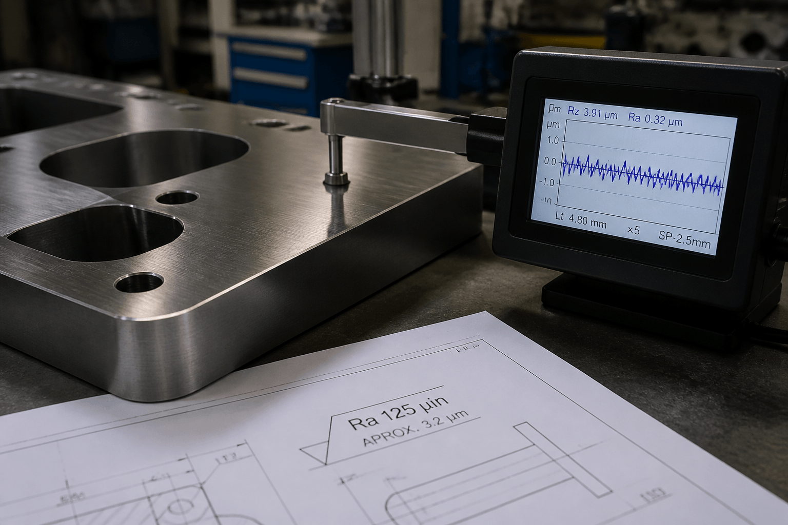
125 surface finish often means Ra 125 microinches, equal to 3.175 micrometers and normally rounded to Ra 3.2 micrometers. That interpretation is conditional: confirm the roughness parameter, units, drawing convention, applicable standard, and measurement conditions before accepting the surface.
A complete requirement might read: Surface A: Ra 3.2 micrometers maximum; lay perpendicular to the direction of motion; measure at the indicated location using the filter, cutoff, and evaluation length required by the referenced drawing standard. By contrast, a note containing only 125 is ambiguous. It does not independently identify Ra or Rz, confirm microinch units, define lay, or tell the inspector how to measure the surface.
What Does a 125 Surface Finish Mean?
On many inch-based engineering drawings, particularly established drawings using conventional roughness notation, 125 is commonly interpreted as 125 microinches Ra. The conversion is:
125 microinches × 0.0254 = 3.175 micrometers, usually expressed as approximately Ra 3.2 micrometers.
However, the number cannot safely be interpreted in isolation. The title block, general notes, surface-texture symbol, parameter notation, units, and governing standard may change its meaning.
| Drawing information | Likely interpretation | Action |
|---|---|---|
| Ra 125 microinches | Arithmetic average roughness, normally a maximum unless the drawing convention states otherwise | Confirm the inspection settings and location |
| Ra 3.2 micrometers | Approximately equivalent to Ra 125 microinches | Use the metric value as specified |
| 125 beside a texture symbol on an inch drawing | Possibly Ra 125 microinches | Check the title block, notes, and referenced standard |
| Rz 125 | An Rz requirement, not an Ra 125 requirement | Confirm units and the standard defining Rz |
| 12.5 beside a texture symbol | A different numerical requirement | Do not assume it means 125 microinches |
A 12.5 surface finish symbol should not be confused with 125. Depending on the units and convention, 12.5 may describe 12.5 micrometers, 12.5 microinches, or another parameter value. Decimal placement and units are therefore critical.
Surface Finish, Roughness, Lay, and Waviness Are Not the Same
Surface finish is a widely used shop and purchasing term, but it can be imprecise. Surface texture is the broader technical concept. It includes roughness, waviness, lay, and sometimes other profile characteristics addressed by the governing specification.
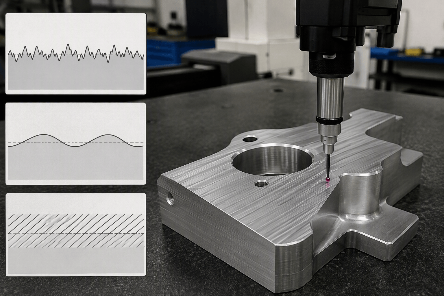
- Roughness consists of relatively fine, closely spaced surface irregularities. Tool feed marks, abrasive action, and material behavior can contribute to the measured roughness profile.
- Waviness consists of more broadly spaced variations. Possible manufacturing causes include vibration, chatter, deflection, distortion, or machine-motion effects. Filtering is used to separate roughness from longer-spaced profile components.
- Lay is the dominant direction or pattern of the texture. Common descriptions include parallel, perpendicular, circular, radial, crosshatched, multidirectional, and approximately isotropic.
Imagine a turned cylindrical face with circular tool marks. The grooves and peaks contribute to roughness, their circular direction is the lay, and a slower repeating rise and fall may be waviness. These characteristics can coexist on the same surface.
This distinction matters for function. A roughness value alone does not establish sealing, friction, wear, coating adhesion, appearance, or cleanability. For example, two surfaces could have similar Ra readings but different lay directions or isolated peaks. Their interaction with a gasket, sliding component, coating, or visible light reflection may therefore differ.
How to Decode the Complete Surface-Texture Callout
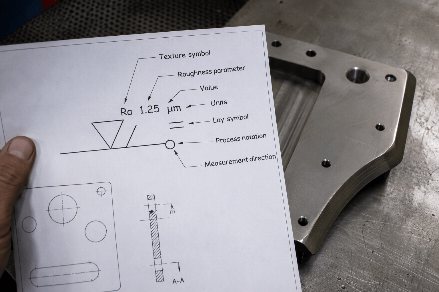
Read the callout as a coordinated set of instructions rather than as a standalone number. Applicable drawing systems, such as the relevant editions of ASME Y14.36 or an identified ISO convention, define how information is arranged around a surface-texture symbol. Measurement terminology and procedures must also follow the inspection standard cited by the drawing or purchasing specification.
- Locate the controlled surface. Follow the leader or extension line. Confirm whether the requirement applies to one face, all around a feature, or several specifically identified areas.
- Identify the parameter and limit. Look for Ra, Rz, or another parameter. Determine whether the value is a maximum, minimum, range, or another form of limit under the stated convention.
- Confirm the units. Inch drawings may use microinches, while metric drawings commonly express roughness in micrometers. Never infer units from the number alone when the title block and notes are inconsistent.
- Interpret the texture symbol. The symbol may indicate whether material removal is required, prohibited, or left unspecified. It does not necessarily prescribe one exact manufacturing process.
- Read process and allowance notes. A machining allowance identifies material reserved for removal; it is not a roughness value. A process indication such as grinding or turning describes an intended method but does not automatically guarantee the specified roughness.
- Check the lay symbol. Lay may be oriented parallel, perpendicular, circular, radial, multidirectional, or in another defined relationship to the drawing view.
Fictional complete example: A drawing identifies Surface A and states “Ra 3.2 micrometers maximum; lay perpendicular to the direction-of-motion arrow; inspect according to Drawing Note 8.” Note 8 identifies the applicable standard, filter, cutoff, evaluation length, and reporting method. This gives production and inspection teams a traceable basis for interpretation.
Fictional ambiguous example: A legacy drawing places “125” near a sealing face without a parameter, units, lay symbol, or referenced standard. The supplier should not silently assume Ra 125 microinches. Clarification is needed because Rz, metric units, or a company-specific convention could produce a substantially different requirement.
Manufacturing methods can produce characteristic patterns: turning may leave circumferential or helical marks, milling can create directional or crossing paths, and grinding may create fine directional texture. Actual results still depend on material, tooling, feeds, speeds, rigidity, geometry, and subsequent finishing. If the requirement applies to a machined interface, see this overview of custom CNC machining when considering how the controlled surface fits into the complete part.
Ra 125 and Rz 125 Describe Different Profile Characteristics
Ra is the arithmetic average of the absolute profile deviations from the mean line over the defined assessment basis. It is useful as a general indicator of average roughness, but averaging can reduce the apparent influence of individual peaks and valleys.
Rz is more sensitive to profile height features because it evaluates peak-to-valley characteristics. Its exact definition and calculation can depend on the governing standard and edition. Consequently, an Rz value must be interpreted under the standard named on the drawing or inspection instruction.
| Characteristic | Ra | Rz |
|---|---|---|
| General concept | Average absolute profile deviation | Peak-to-valley-based profile height |
| Sensitivity | Represents the overall average | More responsive to prominent peaks and valleys |
| Can 125 be assumed to mean this parameter? | No, although Ra is common on some drawings | No; it must be stated or established by convention |
| Direct universal conversion | None. Any ratio is material-, process-, profile-, and method-dependent. | |
Two profiles can have similar Ra values while one contains evenly distributed fine marks and the other contains a few deep valleys. Their Rz values and functional behavior may differ. Approximate Ra-to-Rz ratios found in charts are estimation tools, not a valid substitute for a drawing requirement or measured result.
From Drawing Requirement to Reproducible Inspection
A profilometer does not simply reveal one inherent number. The instrument acquires a profile that can contain roughness, waviness, form, and measurement noise. The setup and filtering determine which components contribute to the reported result.
- Verify the parameter, limit, units, and standard. Resolve missing information before measuring.
- Select the measurement location. Avoid choosing an unusually smooth or rough area unless the drawing specifically controls that location. Small lands, edges, holes, and curved surfaces may limit stylus access.
- Establish the measurement direction. Roughness is commonly measured across, or perpendicular to, the dominant lay because that path usually captures the profile variation most effectively. Another direction may be required by the drawing, part geometry, or function.
- Set the filter and cutoff. The cutoff helps separate shorter-spaced roughness from longer-spaced waviness. An unsuitable setting can include or remove profile features and change the reported result.
- Define sampling and evaluation lengths. A sampling length is an individual profile segment used for assessment under the selected method. The evaluation length is the total length used to determine the reported parameter and may contain multiple sampling lengths.
- Record the result and setup. A number without its measurement conditions may not be reproducible by another inspector.
| Inspection record field | Why it is needed |
|---|---|
| Part and drawing revision | Connects the result to the correct requirement |
| Surface or feature location | Shows exactly where the trace was taken |
| Parameter, limit, units, and measured result | Prevents confusion between Ra, Rz, microinches, and micrometers |
| Filter and cutoff | Defines how profile components were separated |
| Sampling and evaluation lengths | Documents the assessed profile length |
| Stylus direction relative to lay | Makes directional measurements comparable |
| Instrument and relevant tip/setup details | Supports traceability and repeat measurement |
| Number of traces and individual results | Shows how surface variation was evaluated |
Is This 125 Surface Callout Complete?
Use this drawing-to-inspection worksheet before manufacturing or acceptance:
- Is the parameter explicitly identified as Ra, Rz, or another parameter?
- Are the units microinches or micrometers?
- Is 125 a maximum, minimum, target, or range?
- Which drawing and measurement standard, including the applicable edition, governs?
- Is the controlled surface clearly identified?
- Does the symbol require or prohibit material removal?
- Is a machining allowance or required process stated separately?
- Is lay important, and is its direction shown?
- Are filter, cutoff, sampling length, and evaluation length defined or selected by the cited standard?
- Are measurement direction, number of traces, and reporting format established?
Frequently Asked Questions
Is a 125 surface finish the same as 3.2 Ra?
It often is when 125 means Ra 125 microinches. The exact conversion is 3.175 micrometers, commonly rounded to Ra 3.2 micrometers. Confirm that the drawing actually specifies Ra and uses microinch units.
What is the practical difference between a 125 and 250 surface finish?
If both values are Ra in microinches, 250 indicates a higher average roughness than 125: approximately Ra 6.3 micrometers versus Ra 3.2 micrometers. This numerical comparison alone does not predict appearance or functional performance because lay, waviness, profile shape, and process pattern also matter.
Can Ra be converted directly to Rz?
No universal exact conversion exists. Relationships vary with material, manufacturing process, profile shape, filtering, and the standard used to define Rz. Specify and measure the required parameter rather than accepting a general conversion ratio.
Does a 125 callout control lay and waviness as well as roughness?
Not by itself. A properly interpreted 125 roughness value controls the identified roughness parameter. Lay requires directional information, while waviness needs its own parameter or inspection requirement when function demands control of broader-spaced variations.