
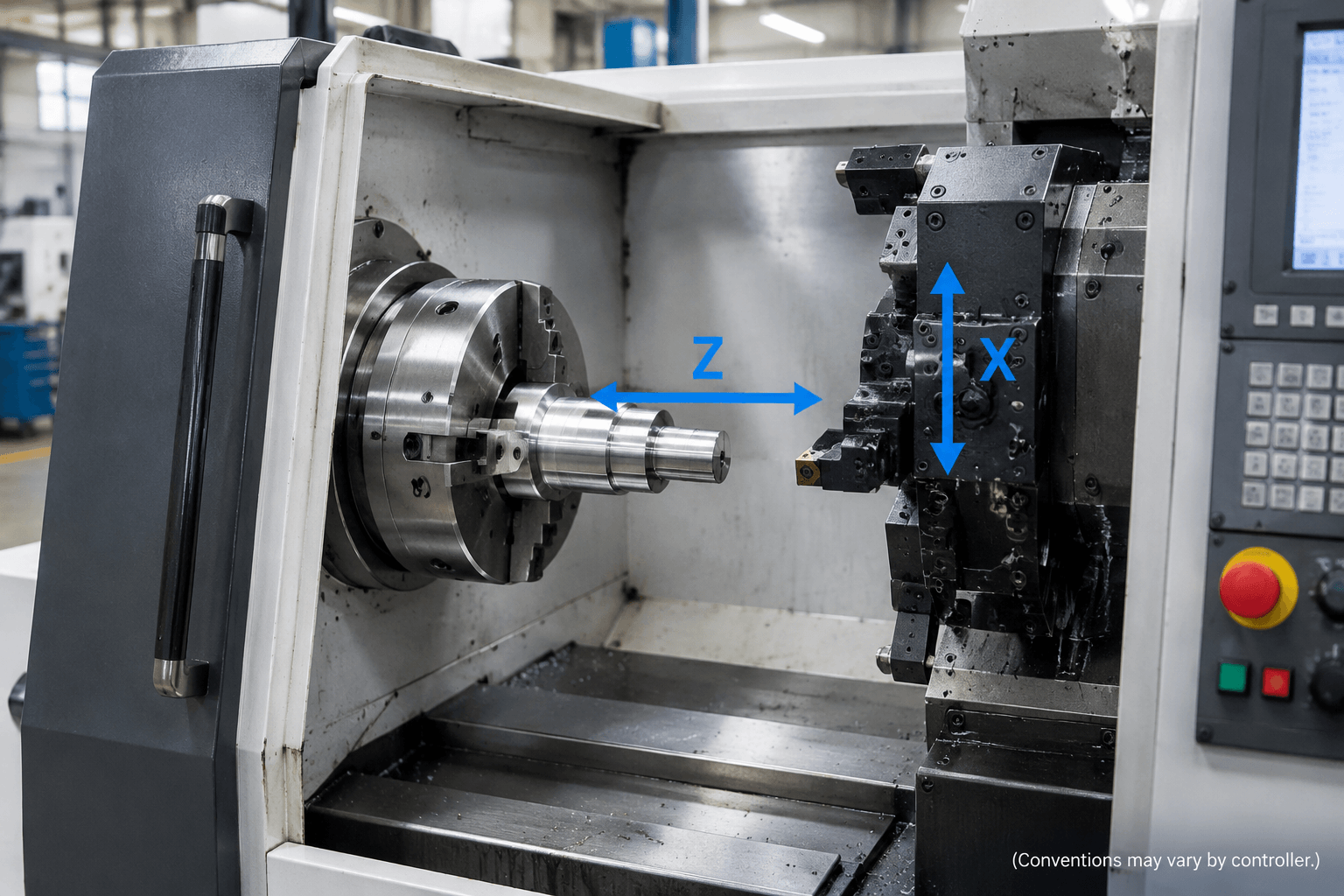
A 2 axis CNC machine is a computer-controlled machine that coordinates two linear movements, commonly X and Z; in industrial use, it usually means a CNC lathe or turning machine. In the typical turning convention, X controls the tool’s radial position and Z moves parallel to the spindle axis, but the coordinate direction and sign convention should always be checked against the machine builder’s documentation.
The spindle rotates the chuck-held workpiece while the cutting tool follows a programmed path. Whether a particular part is a good fit depends less on the machine label alone and more on its geometry, required operations, quantity, material, tolerances, and drawing requirements.
How X and Z work on a typical 2-axis CNC lathe
On a conventional CNC lathe, the workpiece rotates around the spindle centerline. The tool moves in two coordinated linear directions:
- X axis: usually controls radial tool position. Moving in X changes the cutting diameter or positions a tool toward or away from the spindle centerline.
- Z axis: usually moves parallel to the spindle axis. This movement positions the tool along the length of the workpiece.
These descriptions follow the common turning convention, but they are not universal wording for every controller or machine layout. Before programming or reviewing a used machine, confirm the axis orientation, positive direction, work zero, and tool reference system in the machine documentation.
                 X: radial tool movement
                         ↑
                         │ cutting tool
Spindle and chuck |==== WORKPIECE ====| → Z: along spindle axisThe CNC program defines the toolpath and cutting instructions. At an overview level, this includes spindle speed, feed rate, depth of cut, approach and retract movements, and the sequence of operations. A work offset tells the control where the programmed part zero is located. A tool offset compensates for the installed tool’s measured position and geometry. These controller functions support repeatable programming, but they do not replace correct chucking, tool setting, program verification, or machine maintenance.
What can a 2 axis CNC machine make?
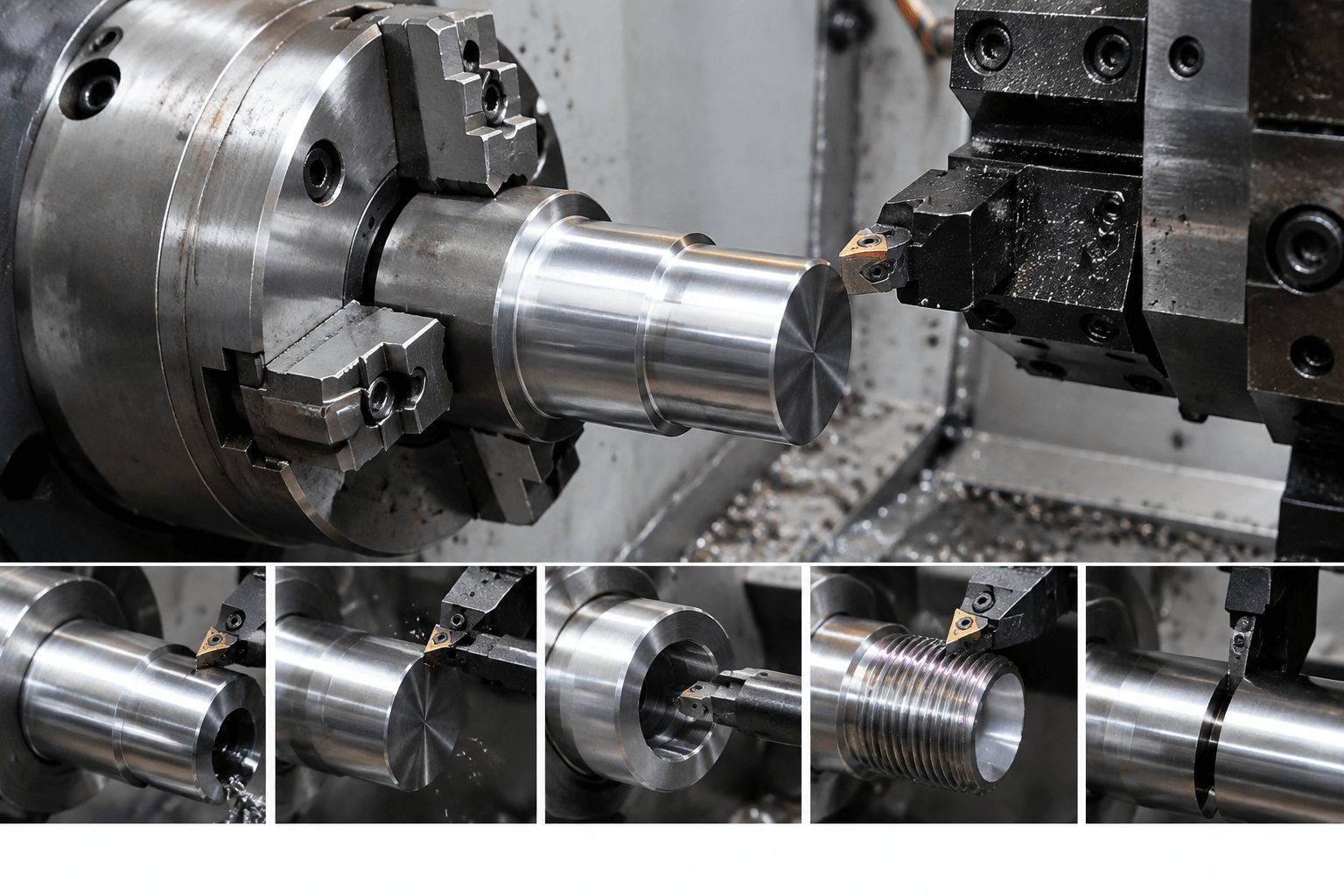
A 2-axis lathe is strongest when the important features are circular, concentric, and aligned with the spindle. It can produce an outside profile, an internal diameter, or an end feature while the workpiece rotates. Coordinated X and Z movement can also create steps, tapers, radii, and other profiles that remain rotationally symmetric.
| Operation | Typical feature produced | Process boundary |
|---|---|---|
| Turning | Outside diameters, shafts, pins, collars, steps, and tapers | The profile should be accessible with the selected external tool and remain suitable for spindle-axis rotation. |
| Facing | A flat end surface or controlled part length | The tool works across the end face from the outside toward the center or as permitted by the setup. |
| Boring | Internal diameters and stepped bores | The workpiece needs a suitable starting hole or drilling operation, plus enough access for the boring tool. |
| Threading | External or internal threads aligned with the spindle axis | Thread form, pitch, relief, tool access, and the drawing specification must be considered together. |
| Grooving | Retaining-ring grooves, reliefs, narrow recesses, and parting features | Groove width, depth, chip evacuation, and tool clearance affect the setup. |
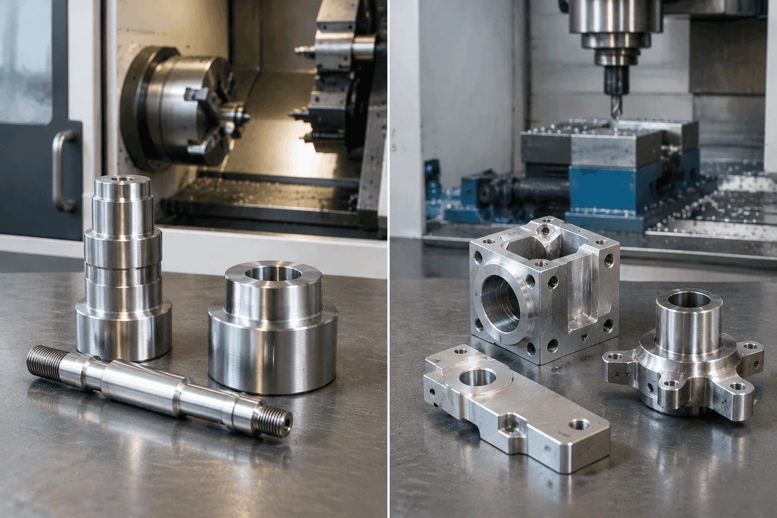
Typical suitable parts include turned shafts, spacers, bushings, bearing-related sleeves, pins, nozzles, threaded studs, and stepped collars. A center hole or axial bore can also be suitable when the required drill, boring bar, or threading tool can reach it.
The boundary appears when a feature is not accessible through the normal X/Z turning envelope. A radial cross-hole, side keyway, milled flat at a particular angular position, off-center hole pattern, or non-rotational pocket normally needs a secondary milling operation, live tooling, indexing, or a machine with additional axes. A freeform three-dimensional surface should not be assumed to be possible simply because the controller accepts a CNC program.
Setup factors that determine repeatable turning results
Axis count describes machine motion, not the complete manufacturing process. Workholding is the first practical consideration. The chuck, jaws, collet, or other fixture must hold the raw material securely without distorting it or blocking the required tool access. Jaw condition, contact length, part protrusion, and support for slender workpieces can all affect stability.
Alignment and runout control are equally important. The part should be seated consistently against the intended locating surface, and runout should be checked using a suitable verification method for the job. Excessive runout can shift the actual cutting position, vary wall thickness, and make a nominally concentric feature difficult to control. A sound setup also confirms that the selected chucking method is appropriate for the material, diameter, length, and cutting forces involved.
Tooling then determines whether the programmed path can be converted into a usable feature. A toolpost may hold external turning tools, facing tools, grooving tools, threading tools, and boring bars. Inserts are selected according to the material and operation, while tool nose geometry, clearance, and reach influence the achievable profile. A small internal diameter may be geometrically possible but impractical if the boring tool cannot enter or remain sufficiently rigid.
Before cutting, the operator or process engineer normally verifies the program origin, work offset, tool numbers, tool offsets, clearance movements, spindle direction, feed, speed, and depth-of-cut instructions. A first-piece review against the drawing can reveal an incorrect offset or tool orientation before the same error is repeated. CNC automation reduces manual movement during production, but it does not automatically remove setup errors, tool wear, chip-control issues, or maintenance requirements.
Choosing between a 2-axis lathe and other CNC configurations
The phrase 2 axis CNC machine can create confusion because axis count does not identify the machine type by itself. A 2-axis CNC lathe and a 2-axis milling setup use different workpiece and tool relationships.
| Machine configuration | Work and tool relationship | Typical fit |
|---|---|---|
| Manual lathe | The workpiece rotates while the operator controls tool movement directly. | One-off or development work where operator-directed turning is appropriate; repeat production depends heavily on manual technique and setup. |
| 2-axis CNC lathe | The workpiece rotates and the tool is programmed mainly in two linear directions, commonly X and Z. | Rotationally symmetric parts with repeated turning, facing, boring, threading, or grooving operations. |
| 2-axis milling setup | The cutting tool rotates while the workpiece is generally fixed; the controlled movements may be two linear directions such as X and Y. | Selected planar or slotting work, depending on the machine and controller. It is not interchangeable with a 2-axis lathe. |
| 3-axis CNC mill | The rotating tool and workpiece use three coordinated linear directions, commonly X, Y, and Z. | Prismatic parts, hole patterns, pockets, flats, and features that require access across more than a turning profile. |
| Multi-axis turning center | Turning may be combined with additional axes, driven tooling, or other feature-access arrangements. | Parts that combine rotational surfaces with cross-holes, milling, angular features, or multiple orientations. |
For a small quantity, programming and setup effort may need to be weighed against the simplicity of manual turning or another process. For repeated production, a stored program and stable workholding can make a CNC turning route easier to standardize, but the result still depends on machine condition, tooling, material preparation, and process verification. A more complex turning center is not automatically the better choice if every feature is already accessible in two-axis turning.
Part-fit decision matrix for 2-axis CNC turning
Use the following matrix as an early screening tool rather than a substitute for reviewing the complete drawing or 3D model.
| Part requirement | Likely process fit | What to confirm |
|---|---|---|
| Outside diameter, stepped shaft, pin, collar, or concentric sleeve | Good candidate for 2-axis turning | Material, stock size, overall length, chucking method, and required diameter and length tolerances. |
| Axial bore, internal diameter, or spindle-aligned thread | Often suitable | Tool access, starting hole, bore depth, thread form, relief, and internal feature tolerances. |
| Rotationally symmetric taper, radius, or contoured profile | Potentially suitable | Whether the profile can be generated in the X/Z plane and whether the tool can reach all transitions. |
| Cross-hole, side slot, keyway, or milled flat | Not usually complete in one 2-axis turning setup | Secondary milling, indexing, live tooling, or another machine configuration. |
| Several holes at different angles or an off-center pattern | Needs additional feature access | Part orientation, angular positioning, drilling access, and whether a 3-axis mill or turning center is more suitable. |
| High-mix, low-quantity work | Requires process comparison | Programming and setup effort versus manual turning, a mill, or an alternative routing. |
| Repeat production of the same turned part | Often a logical CNC application | Program control, workholding repeatability, tool life, batch quantity, and drawing requirements. |
| Tight or critical dimensions | Cannot be decided from axis count | Material behavior, machine condition, tooling, thermal effects, datum strategy, and the required verification method. |
For an early process-fit review, gather the material, largest and smallest diameters, overall length, threads, grooves, holes, critical tolerances, quantity, and any secondary-operation requirements. Also identify whether the part must be completed in one setup or can be transferred to another machine. This information is more useful than selecting a machine based only on a listing, kit description, controller feature, or advertised price.
If the part passes the rotational-symmetry check, review the drawing or 3D model against the operation sequence and confirm whether any secondary operation is required.
For an OEM or ODM process-fit review, provide the part drawing or 3D model, material, required quantity, critical diameters and lengths, threads, holes, tolerances, secondary operations, and delivery requirements. That information allows the manufacturing route to be evaluated before production planning. You can also review custom CNC machining from first sample to repeat production when the part requires a broader machining assessment.
Frequently Asked Questions
Is a 2-axis CNC machine usually a lathe or a milling machine?
In industrial usage, it usually refers to a CNC lathe or turning machine with two coordinated linear axes, commonly X and Z. A 2-axis milling setup may use a different workpiece arrangement and coordinate pair, so the two machine types should not be treated as interchangeable.
What operations can a 2-axis CNC lathe perform?
Typical operations include outside turning, facing, boring, external or internal threading, grooving, and sometimes parting. The exact operation depends on tool access, workholding, material, and the required feature geometry.
Is 2-axis CNC enough for cross-holes, keyways, or complex contours?
Not usually by itself. A cross-hole, keyway, off-center hole, or angular milled feature generally needs a secondary milling or drilling setup, indexing, live tooling, or a multi-axis turning center. A complex contour is feasible only when it remains accessible as a rotationally symmetric X/Z profile.
What is the difference between a 2-axis CNC lathe and a 3-axis CNC machine?
A 2-axis CNC lathe normally rotates the workpiece and controls tool movement in two linear directions. A 3-axis CNC mill normally rotates the cutting tool and coordinates three linear movements, commonly X, Y, and Z, making it more suitable for many prismatic features, pockets, flats, and hole patterns.