
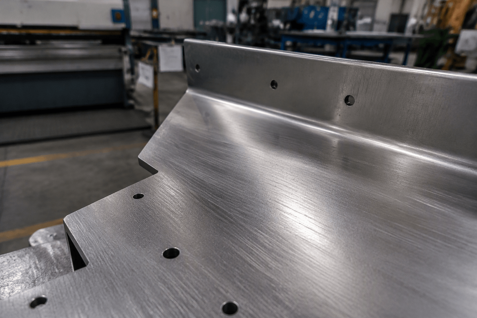
A 250 surface finish usually refers to a surface-roughness value of 250 microinches, but only when the drawing or specification establishes the roughness parameter and unit. In many machining contexts, the intended parameter is Ra, yet “250 surface finish” alone does not universally define 250 Ra, a process result, or a particular standard requirement.
Quick answer: If the requirement is written as Ra 250 µin, it identifies an arithmetic-average roughness value of 250 microinches, equivalent to approximately 6.35 µm. The parameter, unit, measurement direction, evaluation conditions, and acceptance convention must still be stated or referenced.
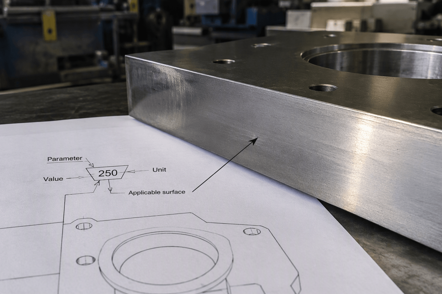
For an OEM drawing, the useful question is not simply whether 250 is rough or smooth. The useful question is whether the callout communicates a measurable surface condition appropriate for the part’s contact, sealing, coating, cleaning, appearance, or handling requirements.
What does a 250 surface finish mean?
A microinch is a unit of length equal to one-millionth of an inch. When a drawing establishes 250 microinches for an Ra requirement, the value summarizes the average deviation of the measured surface profile from its mean line. It does not describe every peak and valley, and it does not by itself define waviness, burrs, scratches, dents, or visual uniformity.
| Callout element | What to verify |
|---|---|
| 250 | Is it a maximum, target, nominal value, or another acceptance limit? |
| Parameter | Is the requirement Ra, or is another profile parameter specified? |
| Unit | Are the units microinches, micrometres, or another unit? |
| Scope | Does it apply to every surface, one face, a sealing land, or a visible area? |
Therefore, a number copied from a generic surface-finish chart should not replace the governing drawing convention. If the documentation says only “250 finish,” ask for clarification before treating it as a controlled inspection requirement.
How should a 250 roughness requirement appear on a drawing?
A complete note identifies the parameter, limit, unit, affected surface, and the conditions used for measurement. Direction is important where machining creates a directional texture. The note should also identify, or reference, the evaluation and acceptance method rather than leaving the inspector to choose an incompatible reporting convention.
For example, the following is an illustrative project-controlled structure, not a universal standard wording:
FACE A: Ra 250 µin MAX (6.35 µm)
Trace direction: perpendicular to the primary tool marks
Measurement locations: designated points shown on the drawing
Method and evaluation conditions: project surface-texture specification [ID/revision]
Acceptance: each reported location must be ≤ 250 µin
This example is more actionable than “250 surface finish” because it separates the required result from the measurement instructions. A general requirement may cover all machined faces, while a functional requirement may apply only to a gasket land, sliding face, coating area, or customer-visible panel. The drawing should make that scope clear.
When is a 250-level finish sufficient for the application?
There is no universal functional rule that makes 250 suitable for every part. Start with the surface’s job, then decide whether the roughness limit is necessary, too loose, or unnecessarily fine. A finer value can increase process planning, finishing, inspection, and rework effort without improving the product if the application does not use that extra control.
| Application | Questions before selecting 250 | Specification guidance |
|---|---|---|
| Noncritical machined face | Does the face only provide clearance or structural support? | A 250-level requirement may be reasonable if appearance and contact function are not critical, but confirm the actual drawing need. |
| Mating or sliding interface | What are the loads, motion, gap, lubrication, and wear conditions? | Use roughness as one input alongside geometry, hardness, material pairing, and contamination control. |
| Seal or gasket surface | What seal material, compression, pressure, and surface geometry are required? | Use the seal or assembly requirement to establish the target; roughness alone does not guarantee leak-tight performance. |
| Coated or painted surface | What preparation and coating system are specified? | Coordinate roughness with cleaning, pretreatment, and coating instructions. Roughness alone does not determine adhesion. |
| Cleanable surface | Are residue retention, access, chemistry, or cleanability validated? | Consider geometry, joints, debris, and cleaning controls; do not use Ra as a substitute for a cleanliness requirement. |
| Visible or handled area | Are tool marks, burrs, discoloration, and tactile feel controlled? | Add appearance or edge requirements where needed. A measured 250 value does not guarantee a uniform cosmetic finish. |
Handling is also separate from roughness. A surface can meet an Ra value and still have a sharp edge, isolated scratch, raised burr, or dent that affects assembly or user contact.
Can a manufacturing process be assumed from a 250 finish value?
No. A roughness callout controls the required surface result; unless the drawing also mandates a process, the manufacturer normally selects a suitable route. A 250-level requirement may correspond to a visibly machined texture in some applications, but it does not predict a uniform appearance or guarantee a particular tool-mark pattern. Tool geometry and condition, feed, speed, toolpath, material, workholding, machine condition, setup stability, and the direction of the cut can all affect the resulting texture.
- CNC milling: cutter diameter, step-over, feed, toolpath, and tool condition influence the visible pattern and measured profile.
- CNC turning: insert geometry, feed, workpiece material, tool condition, and the direction of the turning marks affect the result.
- Drilling and grinding: each produces a process-specific texture and may require additional operations when the functional requirement changes.
- Post-machining finishing: polishing, deburring, blasting, or another treatment may alter texture and appearance, but the required outcome and inspection method should remain clear.
For background on how geometry, material, tolerances, and specified surface requirements affect machining plans, see Custom CNC Machining From First Sample to Repeat Production.
How is a 250 surface finish inspected and accepted?
- Confirm the requirement. Identify the parameter, unit, limit type, affected surface, and whether the requirement is general or local.
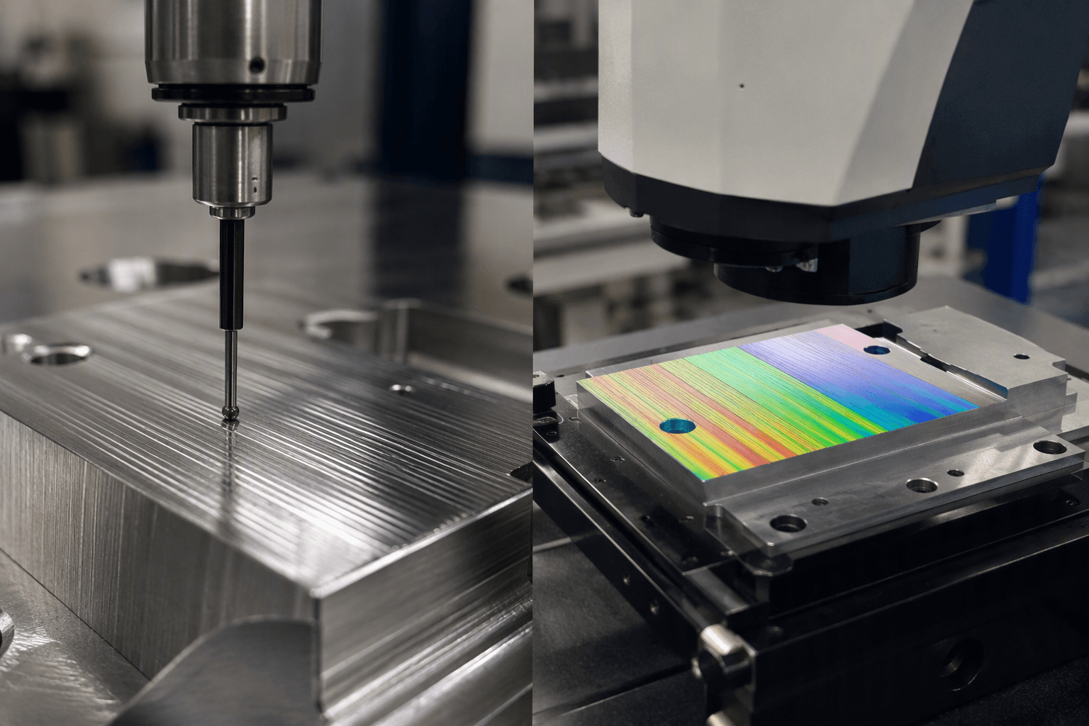
- Select a compatible method. A stylus instrument physically traces a small section of the surface and calculates the stated profile parameter. An optical instrument uses reflected light, imaging, or another non-contact approach to derive surface-profile information. Results from different methods should not be assumed interchangeable without agreement.
- Set the measurement direction. On a directional machined surface, the trace may need to cross the tool marks rather than run along them. The drawing or inspection plan should define the direction where it affects interpretation.
- Align sampling conditions. Cutoff, evaluation length or area, filtering, and the number and location of readings can affect the reported value. Use conditions compatible with the governing requirement.
- Compare with the acceptance convention. A note such as “Ra 250 µin maximum” is different from a target value or an average across several locations. Record the actual locations and reported values.
- Separate measurement from appearance. Visual inspection and tactile comparison can identify obvious marks or damage, but they do not replace a measured roughness check when the drawing requires one.
Before production release, align the supplier and buyer on the measurement location, direction, method, and reporting format. This prevents a part from being judged against a different interpretation of the same short finish number.
If a drawing still says only “250 surface finish,” a technical review can help clarify whether the callout is measurable and appropriate for the part’s intended function. Share the part drawing or surface note, the material, the surfaces covered, and the functional reason for the requirement—such as contact, coating, cleaning, sealing, or appearance. Yishang supports OEM and ODM custom manufacturing and can review the finish definition in the context of the wider part specification.
Frequently Asked Questions
Is a 250 surface finish the same as 250 Ra?
Not automatically. It is commonly intended to mean 250 microinches Ra when the drawing or specification establishes both Ra and the unit. The phrase alone is incomplete.
Is 250 surface finish considered rough or smooth?
It describes a measured roughness level, not a universal visual grade. Whether it is suitable depends on the surface function, material, process, appearance requirement, and measurement convention.
Can a 250 finish be used on a sealing or mating surface?
Possibly, but the answer must come from the seal or interface requirement. Contact geometry, compression, load, material pairing, motion, and contamination can matter as much as roughness.
Why can a surface look smooth but not meet the specified roughness value?
Human vision and touch may miss directional peaks, short sampling areas, isolated marks, or differences in measurement direction. Appearance is not a substitute for a compatible instrument and defined inspection method.