
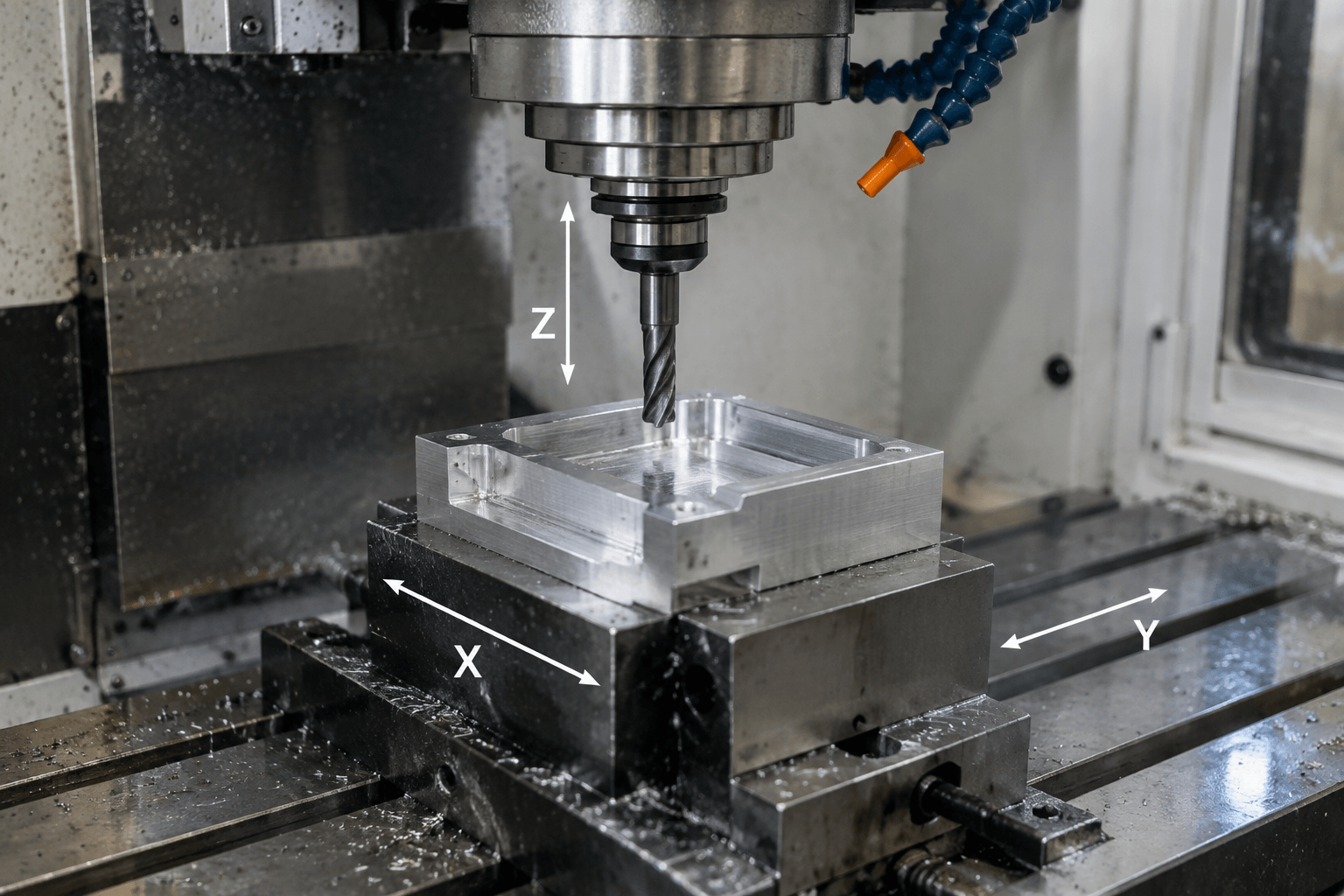
A 3 axis machine is a CNC machine that controls movement along three linear axes: X, Y, and Z. It is generally suitable when cutting tools can reach the required surfaces from one direction, although additional setups may be used to expose other faces.
The practical question is not simply whether a part looks complex. It is whether the spindle, toolholder, fixture, and part orientation provide a clear path to every machined feature.
What X, Y, and Z Describe
The three axes describe programmed linear motion within the machine coordinate system. X commonly represents left-to-right travel, Y represents front-to-back travel, and Z represents movement toward or away from the workpiece. On a typical milling setup, Z is aligned with the spindle axis.
X: left and right across the machining plane
Y: forward and backward across the machining plane
Z: tool approach, cutting depth, and withdrawal
Axis direction should not be confused with which component moves. One 3-axis CNC mill may move the table in X and Y while moving the spindle in Z. Another configuration may place more of the linear travel in the spindle head, table, or gantry. The controller coordinates the commanded relative movement between the cutting tool and workpiece regardless of how the machine distributes that motion.
Workpiece orientation is a separate matter. A vise, fixture plate, vacuum fixture, or other workholding device establishes how the part is presented to the tool. Axis count alone does not mean that the workpiece is always stationary, nor does it describe the machine’s work envelope, spindle characteristics, rigidity, tooling, or achievable tolerance.
Features a 3-Axis CNC Mill Can Reach
Imagine a rectangular metal housing clamped with its main face upward. In this orientation, a 3-axis milling machine can move the cutter across the top plane while controlling cutting depth. This supports many common operations:
- Face milling: producing or refining an accessible flat surface.
- Pockets and recesses: removing material inside boundaries that are open toward the spindle.
- Slots and channels: cutting straight or contoured paths where the tool has sufficient entry and clearance.
- Vertical holes: drilling, boring, reaming, countersinking, or tapping features aligned with the spindle.
- External contours: machining reachable edges and profiles around the part.
- Engraving: adding accessible text, identification marks, or shallow linework.
- Three-dimensional surfaces: following programmed X, Y, and Z toolpaths with suitable cutters, provided the tool can approach the surface without collision.
A freeform surface does not automatically require a rotary axis. A ball-end cutter can machine many slopes and curved surfaces on three axes when all relevant surface normals remain accessible from the chosen orientation. Tool diameter, holder clearance, tool length, surface finish requirements, and the surrounding geometry still affect feasibility.
CNC turning is conceptually different. Turning rotates the workpiece against a cutting tool and is often appropriate for predominantly rotational geometry such as shafts, bushings, and cylindrical profiles.
Where One-Setup Access Ends
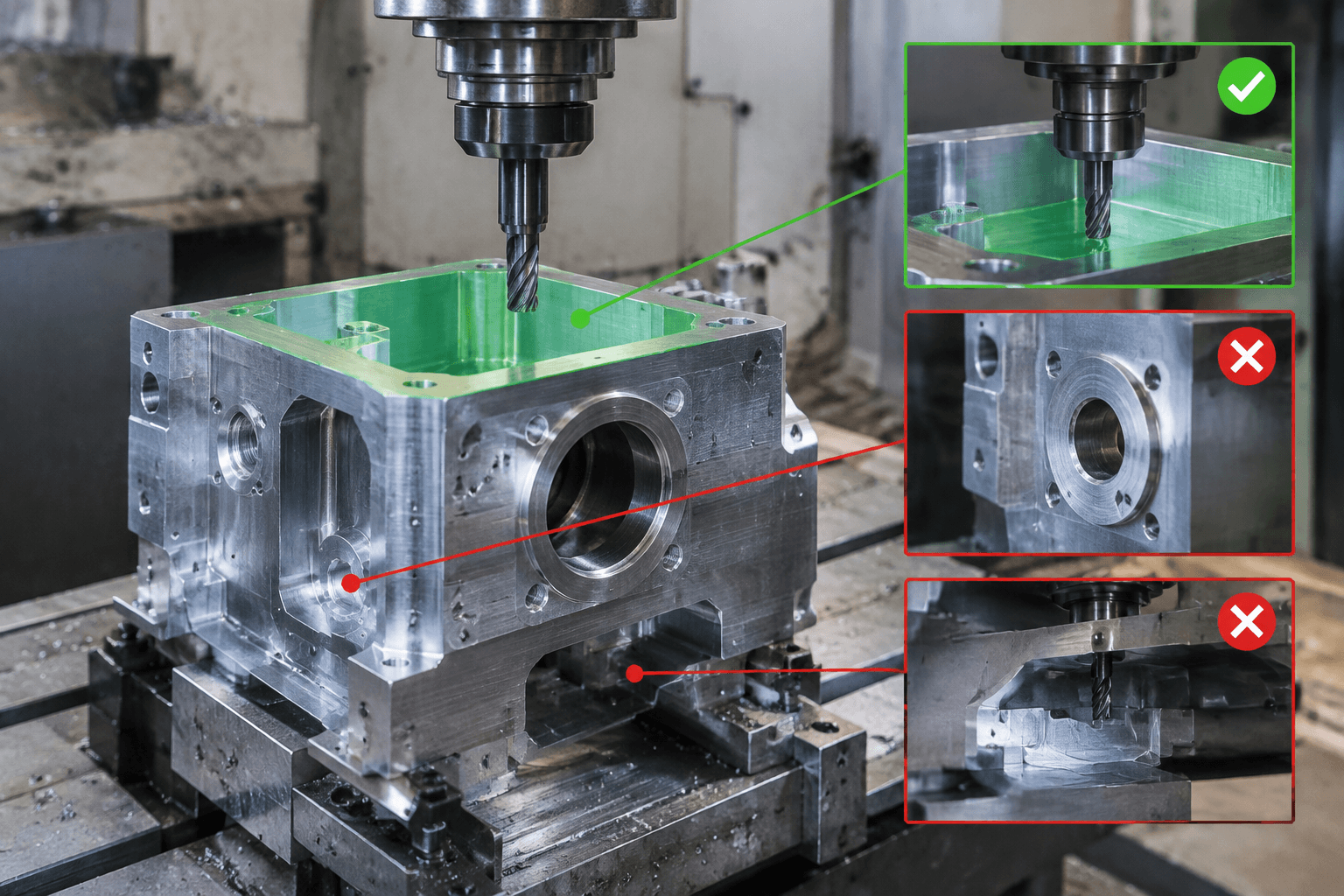
The spindle on a conventional three-axis setup approaches the part along one fixed orientation. Features facing that approach direction are usually the most direct to machine. Features facing sideways, downward, behind an obstruction, or around a curved body may be inaccessible in the same setup.
Reachable from above: top pockets, vertical holes, open slots, top-facing contours, and accessible sculpted surfaces.
Blocked or differently oriented: horizontal side holes, pockets on the back face, enclosed reverse features, and surfaces hidden by a wall, clamp, or toolholder.
A side hole in the hypothetical housing cannot normally be drilled while the housing remains flat and the spindle remains vertical. The part may need to be turned onto another face, held in an angle fixture, positioned by a rotary axis, or approached with specialized tooling. Each option changes workholding, programming, and inspection considerations.
Undercuts require particular attention. A T-slot cutter, lollipop cutter, or other specialized tool can reach some undercut forms from an available opening. It cannot solve every reverse-facing feature, especially when adjacent walls prevent the cutter or holder from entering and moving through the required path.
Deep pockets present a different limitation. Their surfaces may face the spindle, yet depth and narrow openings can require long tool overhang. Deflection, vibration, chip evacuation, holder interference, and reduced cutting conditions may become more important than nominal axis count. Reorienting the part, changing the feature design, or using another process may be more practical.
Reclamping, Indexed Rotation, and Simultaneous Motion
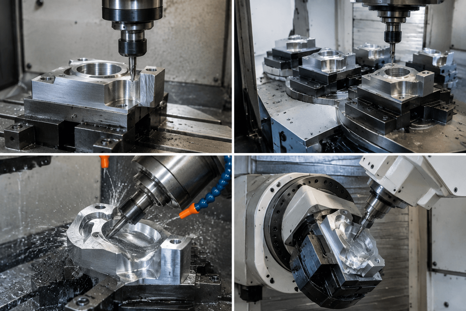
When a feature is not accessible, the next step is to determine whether the part only needs a new orientation or requires controlled rotation during cutting. These are different process strategies.
| Strategy | What moves between or during cuts | Typical use | Key consideration |
|---|---|---|---|
| Multiple 3-axis setups | An operator or automation reclamps the part in a new orientation; cutting remains three-axis | Features on several distinct faces | Fixtures and datums must locate the part consistently after repositioning |
| Indexed 3+1 machining | A rotary axis positions the part, then remains locked while three-axis cutting occurs | Repeated access to angled faces or features around a body | Indexing reduces manual reorientation but is not simultaneous 4-axis cutting |
| Simultaneous 4-axis machining | One rotary axis moves in coordination with X, Y, and Z during the cut | Wrapped profiles, helical paths, or continuous machining around a rotational axis | Toolpath, workholding, control capability, and collision clearance must support coordinated motion |
| 5-axis machining | Two rotary degrees of freedom provide additional tool or part orientation, either indexed or simultaneous | Multiple angled planes, intricate surfaces, or access that one rotary axis cannot provide | Five-axis access does not by itself guarantee a better tolerance, finish, cycle time, or price |
Extra three-axis setups can be entirely appropriate for a prismatic part with a manageable number of faces. However, every reclamping operation introduces a datum-transfer and inspection question. The relevant drawing tolerances may reference features created in different orientations, so process planning must define how those relationships will be established and verified.
Indexed machining can reduce manual handling and keep several operations within one workholding arrangement. Simultaneous rotary machining becomes relevant when rotation is part of the cutting path rather than a positioning step. The preferred method depends on geometry, tolerance relationships, quantity, fixture strategy, available machine configuration, and programming effort.
Can This Feature Be Machined on Three Axes?
Start with the drawing or 3D model and identify the direction from which each feature must be approached. Then consider the cutter body, holder, spindle, clamps, and surrounding part geometry. The following matrix is a screening tool, not a substitute for a machine-specific review.
| Drawing feature | Likely process fit | What to review |
|---|---|---|
| Top-facing pocket, slot, or hole | Often one 3-axis setup | Depth, corner radius, tool entry, chip clearance, and clamp position |
| Features on the top and one or more side faces | Additional 3-axis setups or indexed positioning | Datum transfer, fixture access, and relationships between faces |
| Repeated holes around a cylindrical body | Indexed rotary positioning may be efficient | Angular location, rotary workholding, and whether cutting occurs only while locked |
| Continuous profile wrapped around an axis | Potential simultaneous 4-axis application | Coordinated rotary toolpath, support of the part, and collision risk |
| Multiple compound-angle surfaces | Multiple fixtures, indexed 5-axis, or simultaneous 5-axis may be considered | Required orientations, tool reach, surface transitions, and tolerance relationships |
| Reverse-facing undercut | Specialized cutter, reorientation, another machining method, or design revision | Opening size, obstruction, cutter-neck clearance, and holder access |
| Predominantly rotational part | CNC turning, possibly followed by milling | Whether the main geometry is generated more naturally by rotating the workpiece |
Machine configuration and workholding can change the conclusion. A feature that fits one 3-axis machine may exceed another machine’s travel, clearance, spindle, tooling, or fixture arrangement. Material, blank condition, heat treatment, required finish, tolerance scheme, inspection method, and production quantity also influence process selection.
For a manufacturability review, provide the part drawing or 3D model, material, required feature orientations, tolerance requirements, and quantity. These inputs allow the geometry to be assessed for one-setup 3-axis machining, additional orientations, or rotary-axis access. Submit them through the CNC machining project page.
Frequently Asked Questions
Is a 3-axis CNC machine the same as a 3-axis milling machine?
The terms are often used interchangeably when discussing CNC mills with X, Y, and Z linear motion. However, “3-axis CNC machine” is the broader expression, while “3-axis milling machine” identifies milling as the cutting process. The machine’s architecture still determines whether the table, spindle head, or another assembly provides each movement.
Can a 3-axis machine cut features on the sides of a part?
Yes, if the part is reoriented so the side faces the spindle, or if suitable specialized tooling and clearance are available. Side features are generally not reachable in the original top-facing setup with a fixed vertical tool orientation. Repositioning requires a suitable fixture and a datum strategy for controlling relationships between features.
What is the difference between 3-axis, indexed 3+1, and simultaneous 4-axis machining?
Three-axis machining coordinates linear X, Y, and Z motion. Indexed 3+1 adds a rotary axis that positions and locks the part before three-axis cutting. Simultaneous 4-axis machining moves that rotary axis while cutting, allowing toolpaths that wrap around or follow a rotating workpiece.
What factors affect 3-axis CNC machine price?
For machine acquisition, price can vary with work envelope, construction, spindle and control configuration, automation, tooling interfaces, options, support, and supplier terms. For outsourced parts, the relevant machining price depends on material, stock form, geometry, setups, cutting time, tooling, tolerances, finish, inspection, and quantity. Axis count alone does not establish either price.