
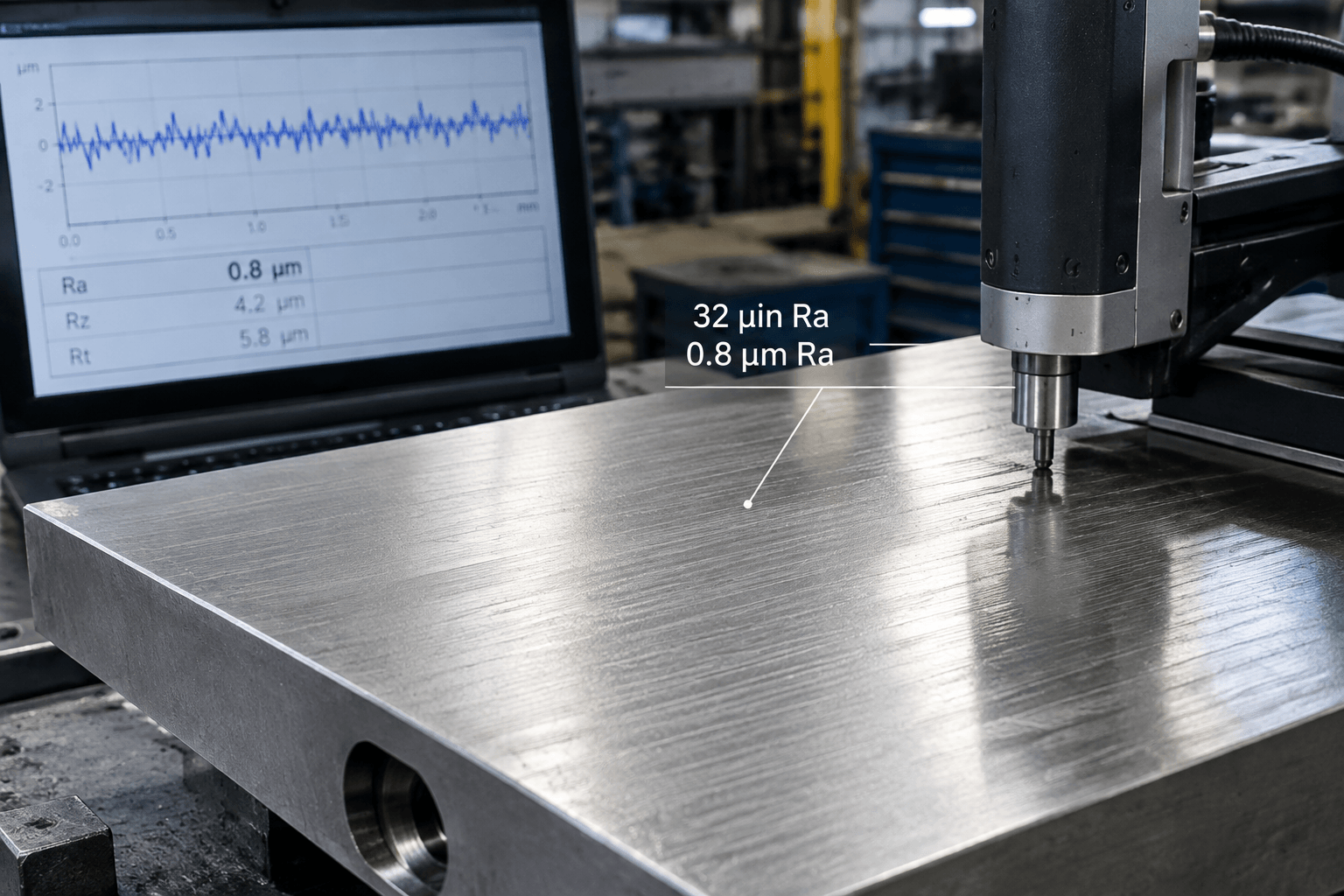
A 32 microinch finish normally means 32 µin Ra when the roughness parameter is explicitly identified as Ra. Its metric equivalent is approximately 0.8 µm Ra. The value describes arithmetic average surface roughness, not a guaranteed appearance, lay pattern, peak height, sealing performance, friction level, or manufacturing process.
A drawing should therefore state both the parameter and the units. A bare callout such as “32 finish” may be understood informally, but it is ambiguous during technical review because it does not confirm whether the requirement is Ra, an older RMS/Rq convention, or another interpretation.
What Does a 32 Microinch Finish Mean?
Ra is the arithmetic average of the absolute profile deviations from a mean line over the evaluated surface trace. In practical terms, it reduces many measured profile points to one average roughness value. The lower the Ra value, the smaller the average profile deviations, but that does not necessarily mean the surface is better for every application.
The unit conversion is:
32 µin × 0.0254 µm/µin = 0.8128 µm
For drawing and manufacturing discussions, this is conventionally expressed as 0.8 µm Ra. Accordingly, 32 µin Ra and 0.8 µm Ra communicate the same nominal roughness requirement when the rounding convention is understood.
AA, meaning arithmetic average, and CLA, meaning center-line average, are older terms commonly associated with the same general arithmetic-average concept represented by Ra. Legacy documentation may use these terms, but the original drawing convention should still be reviewed rather than silently modernized.
Why “32” by itself is incomplete
The number alone leaves two important questions unanswered:
- Which parameter? Ra, Rq, Rz, Rt, and Rmr describe different characteristics.
- Which units? A value in microinches is not numerically interchangeable with the same value in micrometers.
A clear requirement identifies the controlled surface and states “32 µin Ra” or “0.8 µm Ra.” If an older drawing uses “32 RMS,” “32 AA,” or only a triangle-style finish symbol, the designer, manufacturer, and inspector should agree on the intended interpretation before production.
What 32 µin Ra Does—and Does Not—Describe
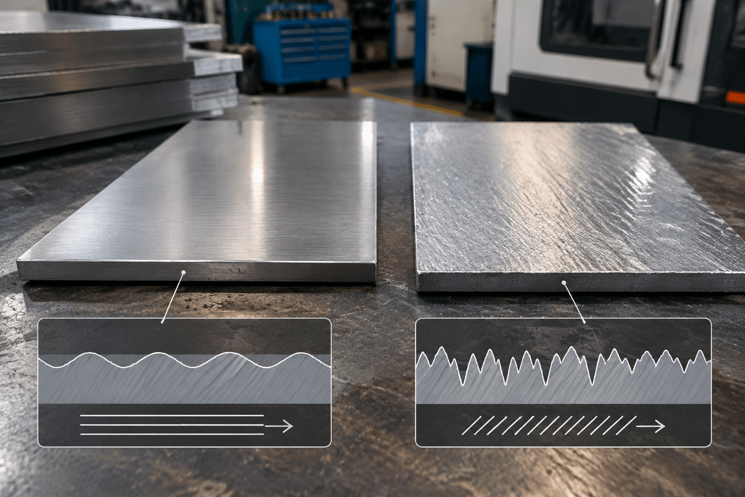
Ra is useful because it provides a compact and widely recognized measure of average roughness. However, averaging also removes information. Different profile shapes can produce the same Ra result even when their peaks, valleys, spacing, direction, and visual texture differ.
| Illustrative surface | Profile characteristics | What Ra may not reveal |
|---|---|---|
| Surface A | Closely spaced, relatively uniform tool marks | Direction and spacing of the repeating lay |
| Surface B | More widely spaced features with occasional deeper valleys | Valley distribution and isolated profile features |
| Surface C | Similar average roughness with a different lay direction | How texture direction interacts with motion, sealing, or appearance |
These descriptions are conceptual illustrations, not measurement data or guaranteed process results.
A 32 µin Ra result therefore does not, by itself, guarantee:
- a uniform visual or cosmetic appearance;
- a particular direction of machining marks;
- the absence of isolated scratches, pits, burrs, or deep valleys;
- acceptable sealing, bearing, fatigue, friction, or wear behavior;
- sanitary performance or cleanability;
- coating adhesion or a specific post-coating appearance.
Ra compared with Rq, Rz, Rt, and Rmr
Rq, also called RMS roughness in some contexts, is the root mean square of profile deviations. Because its calculation gives greater influence to larger deviations, it is not numerically interchangeable with Ra. There is no universal conversion factor that safely converts a legacy RMS/Rq requirement to Ra for every surface.
Rz describes peak-to-valley characteristics under the definition and standard specified for the measurement. Rt addresses the total profile height over the evaluation length. Rmr, the material ratio, can help describe how much of the profile would support contact at a defined level. These parameters may be relevant when an average alone does not represent the functional concern.
Is 32 µin Ra Enough for This Surface?
The correct requirement begins with the surface’s function. A finer Ra value is not automatically better: unnecessary refinement may affect processing, dimensions, edge condition, production time, and cost without improving the intended function.
| Surface function | What 32 µin Ra communicates | Information that may also be needed |
|---|---|---|
| General machined face | An average roughness limit or target, as defined by the drawing | Controlled area, exclusions, and whether isolated defects are acceptable |
| Mating or locating face | Average texture magnitude | Flatness, dimensional requirements, contact area, and lay where functionally relevant |
| Sealing surface | Only the average roughness | Seal type, lay direction, waviness, allowable defects, and possibly another profile parameter |
| Bearing or sliding surface | One aspect of the texture | Motion direction, lubricant-retention needs, plateau or valley characteristics, and applicable functional parameters |
| Fatigue-sensitive area | Average roughness, but not isolated stress-raising features | Limits on scratches, tool marks, edge transitions, or peak-and-valley characteristics |
| Surface receiving a coating | Pre-coating average roughness if that stage is identified | Measurement stage, preparation method, cleanliness, and coating-specific requirements |
| Visible or cosmetic face | No guarantee of visual uniformity | Approved appearance criteria, viewing conditions, grain or lay direction, and defect limits |
Sheet metal cosmetic finishes, brushed patterns, and coated appearances should not be assumed equivalent to a machined 32 µin Ra surface. They may involve different processes, texture scales, inspection methods, and acceptance criteria.
Why the Actual Part Affects the Result
Whether a surface can be produced and verified at 32 µin Ra depends on more than the nominal callout. Material condition, part geometry, cutting conditions, tool access, workholding, and the location being measured all affect the resulting texture.
| Factor | Possible effect on the surface |
|---|---|
| Material and material condition | Chip formation, inclusions, hardness variation, tearing, or built-up edge can change the measured and visible texture. |
| Tool condition and geometry | Wear, edge condition, runout, and tool geometry can alter feed marks, peaks, and isolated defects. |
| Feed, speed, and engagement | These conditions influence mark spacing and profile shape, but their effects depend on the operation, tool, and workpiece. |
| Machine, fixture, and vibration | Deflection or chatter can introduce periodic texture or waviness that Ra alone may not adequately describe. |
| Thin walls and flexible features | Part movement during cutting can make texture less consistent across the controlled area. |
| Internal or obstructed features | Restricted tool and instrument access may affect both manufacturing strategy and inspection location. |
| Interrupted cuts | Changing tool engagement can create texture transitions that are not represented by a single conveniently located trace. |
Turning commonly produces a circumferential or helical lay, while milling can leave directional, crossing, or repeating cutter marks. The operations should not be treated as visually or functionally interchangeable merely because both surfaces measure 32 µin Ra. Their suitability depends on the part and its intended use.
When the primary machining operation cannot provide the required surface, grinding, honing, lapping, or polishing may be considered as secondary operations. These processes can change dimensions, edge radii, local form, and lay, so they must be reviewed as part of the manufacturing plan rather than added as an assumed cosmetic step. The same production review applies when selecting conditions for custom CNC machining.
How to Define and Verify a 32 µin Ra Requirement
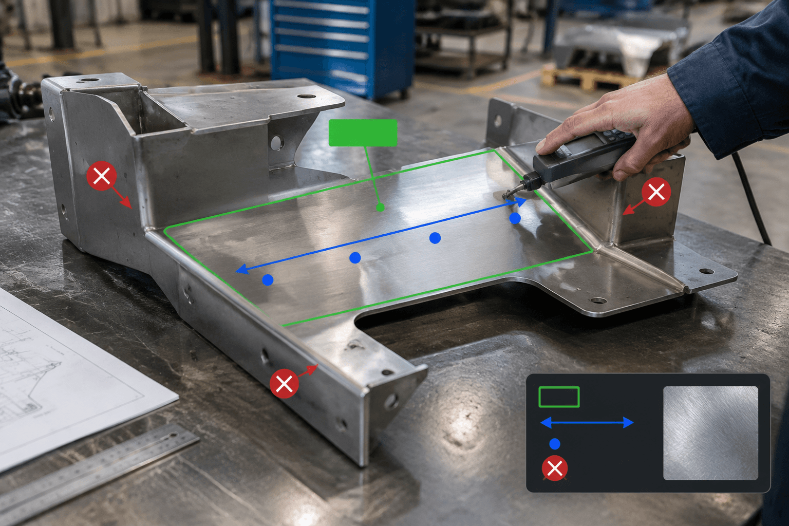
A useful callout makes the requirement inspectable. Drawing terminology and surface-texture symbols should be applied consistently with the governing drawing requirements, such as the applicable provisions of ASME B46.1 where specified. Referencing a standard does not replace the need to identify the actual surface, parameter, units, and acceptance conditions.
Drawing-definition illustration
Contact and non-contact measurement
A contact profilometer uses a stylus to trace the surface and calculate the selected roughness parameter. Stylus geometry, access, trace direction, instrument settings, and the distinction between roughness and longer-wavelength form can affect the reported result.
Non-contact optical methods evaluate surface topography without dragging a stylus across the part. They can be useful where contact or access is problematic, but their results should not be assumed equivalent to contact measurements without an agreed method and suitable correlation for the surface being inspected.
Practical inspection workflow
- Confirm that the callout states Ra and the correct units rather than only “32.”
- Identify the controlled faces and any excluded regions on the drawing.
- Review the expected lay and select a measurement direction appropriate to the requirement.
- Choose accessible, representative sampling locations rather than only the easiest point to reach.
- Use the agreed instrument, cutoff, evaluation length, filter, and parameter settings.
- Record individual results and their locations so variation across the surface is visible.
- Evaluate scratches, pits, burrs, waviness, and appearance under their own acceptance criteria instead of assuming Ra covers them.
Legacy drawings require particular care. A callout written as RMS/Rq should not be relabeled Ra through a fixed conversion, and an obsolete triangle symbol cannot always be assigned an exact modern Ra value without additional design context.
Clarify the Callout Before Production
Before treating 32 µin Ra as a stand-alone appearance or performance requirement, provide an annotated drawing showing the controlled surfaces, the material and material condition, and the function of each specified face. Also identify the required roughness parameter and units, plus any lay, sampling, inspection, or appearance requirements that apply. This review helps determine whether the callout is complete, inspectable, and appropriate for the intended manufacturing route.
Where RFQ Assumptions Create Cost and Production Risk
Many sheet metal fabrication problems begin before production starts. If drawings, tolerances, finish expectations, material grades, or assembly requirements are unclear, suppliers may quote based on different assumptions. That can make prices difficult to compare and may lead to rework, cosmetic rejection, assembly misalignment, or production delays later.
For OEM buyers, the goal is not simply to request the lowest price. The goal is to make sure each supplier is quoting the same manufacturing reality. Before confirming an order, clarify which dimensions are fit-critical, which surfaces are cosmetic, whether prototypes must match batch-production conditions, and how finished parts will be inspected.
Frequently Asked Questions
What coating thickness details should buyers define before requesting a quote?
Buyers should define the functional requirement, drawing notes, critical dimensions, material or process expectations, and any inspection points related to coating thickness. This helps suppliers quote the same manufacturing scope instead of making different assumptions.
How can masking areas affect cost, fit, or lead time?
masking areas can change tooling, forming, welding, finishing, inspection, or rework requirements. If buyers do not clarify it early, two supplier quotes may look comparable while covering different production risks.
Why should powder coating be reviewed before prototype approval?
powder coating may look acceptable on a single sample but become harder to control during batch production. Buyers should confirm whether the prototype reflects the same process, finish, and inspection conditions expected for production.
What inspection points matter most for 32 microinch finish projects?
Important inspection points usually include fit-critical dimensions, holes or mating areas, cosmetic surfaces, finish build-up, welded or formed features, and any dimensions that affect downstream assembly. These points should appear in the RFQ or drawing notes.
How can buyers reduce assembly clearance risk before batch production?
Buyers can reduce risk by clarifying drawings, locking key material and finish assumptions, defining inspection timing, approving a representative sample, and confirming which dimensions or surfaces require tighter process control.
How can Yishang help review 32 microinch finish requirements?
Yishang can review drawings, RFQ notes, material requirements, tolerance expectations, finish details, samples, and assembly needs to identify unclear assumptions before quoting or batch production.