
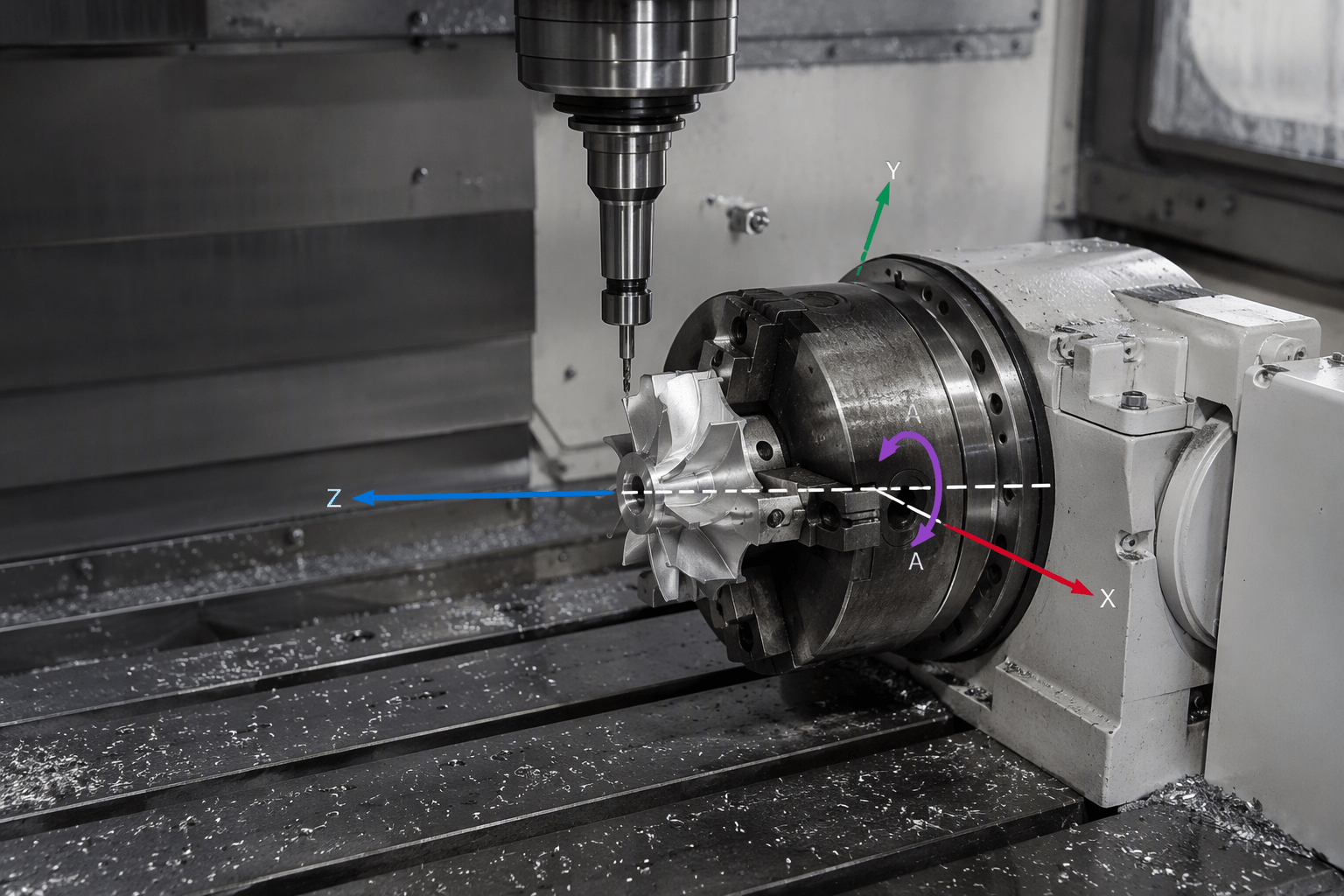
A 4th-axis CNC adds controlled rotary motion to a machine’s linear movements. In a common axis convention, the rotary axis is called A because it turns around X. That designation describes the axis of rotation, not which component must physically move: depending on the machine layout, the workpiece, tool, or an assembly may rotate. The key distinction is whether the rotary axis only positions the part between cuts or coordinates with linear motion while cutting.
With indexed machining, the workpiece moves to a selected angle and is held there while the tool cuts. With simultaneous rotary machining, the rotary axis moves in coordination with one or more linear axes during the cut. Which mode a setup can perform depends on the machine configuration and its control, CAM software and postprocessor, rotary hardware, and workholding. The label “4-axis” alone does not establish that every motion is available.
What the fourth axis rotates
Many CNC machines control three linear directions, conventionally called X, Y, and Z. A fourth controlled axis adds rotation around a defined line. When that line is parallel to X, the axis is commonly designated A. Other layouts and conventions may use a different rotational-axis designation, so confirm the machine’s coordinate system rather than relying on the axis name alone.
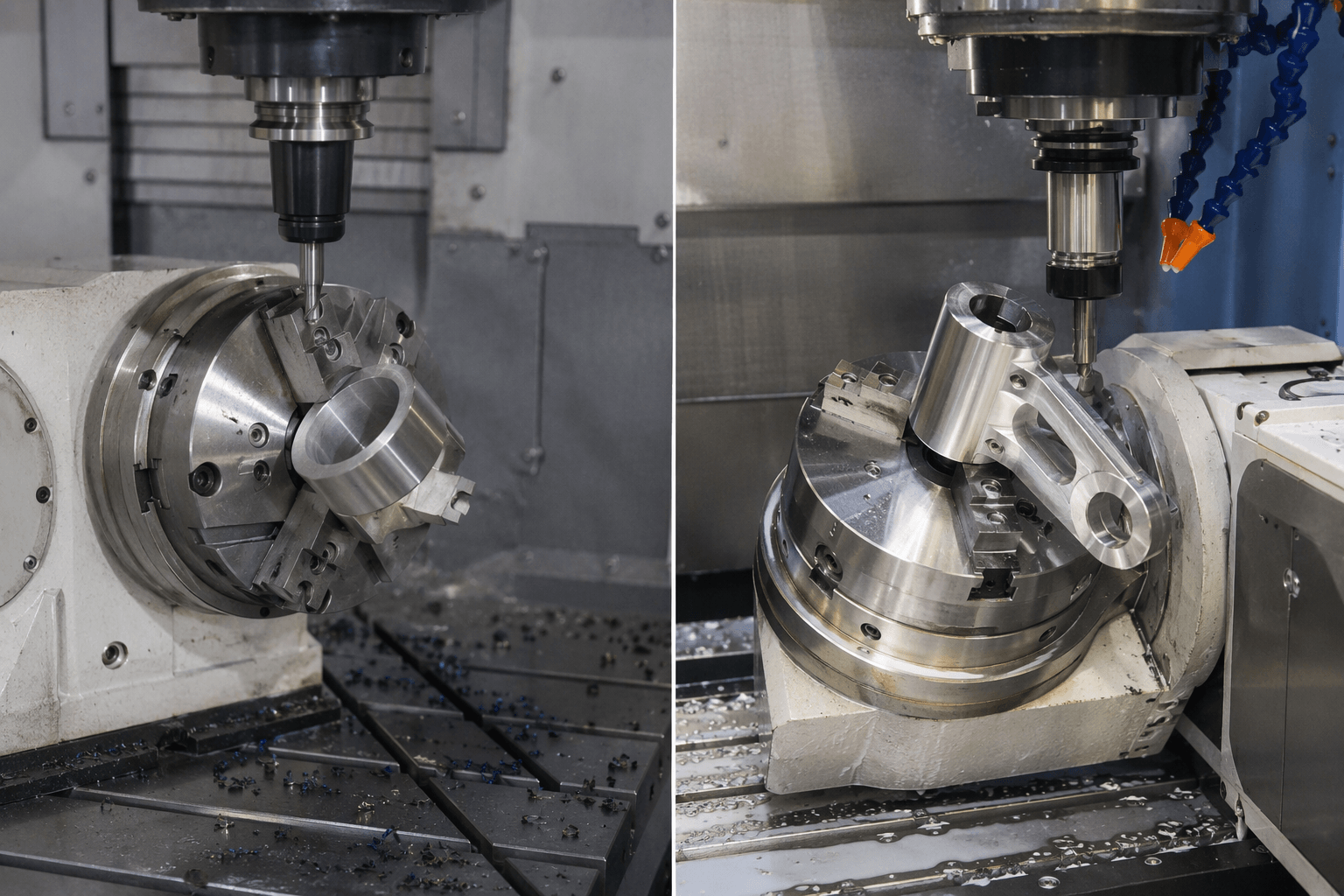
A rotary unit can turn a workpiece so different sides face the cutting tool. In another machine arrangement, the tool or a larger machine assembly may provide the rotary movement. The practical question is not simply “Does it have an A-axis?” It is which component moves, around what centerline, and how that movement interacts with the machine’s linear axes and toolpath.
Fourth-axis CNC is used in both router and mill contexts. Those names describe different machine contexts, not different principles of rotary motion. A rotary accessory or machine configuration must still be checked against the intended part, control, software, and workholding. A general description of a fourth axis does not establish compatibility with a particular machine.
Indexed positioning and simultaneous rotary cutting
Indexed positioning and simultaneous rotary cutting both use rotary motion, but they describe different motion during the cutting process. In indexed work, the axis moves to an angle, stops, and holds position while machining proceeds. In simultaneous work, the rotary axis changes position while the tool is cutting, coordinated with linear movement to follow the programmed geometry.
| Operation | Motion during cutting | Typical feature relationship | What to verify |
|---|---|---|---|
| Indexed positioning | The rotary axis moves between programmed positions, then remains stationary during each cut. | Separate features can be cut at selected orientations around a part. | Whether the machine can position and hold at the required orientations, and whether the planned tool access and workholding are suitable. |
| Simultaneous rotary machining | The rotary axis and one or more linear axes move together during a cut. | A toolpath can follow geometry that requires coordinated rotation as well as linear travel. | Whether the controller, CAM strategy, postprocessor, machine configuration, rotary hardware, and setup support the required coordinated motion. |
Continuous rotation by itself does not prove that a machine is performing simultaneous multi-axis cutting. A rotary axis may turn continuously for a particular operation, but the defining capability in simultaneous machining is coordinated motion between the rotary and linear axes during the toolpath. Confirm what motion the complete machine and software workflow supports.
Some configurations use a rotary axis in place of, or by repurposing, a linear-axis connection. That is a machine-layout tradeoff, not a universal definition of fourth-axis CNC. A setup may retain all three linear movements, while another may limit or repurpose one. Check which axes remain available and how the machine is configured for the intended job.
Match part features to the required motion
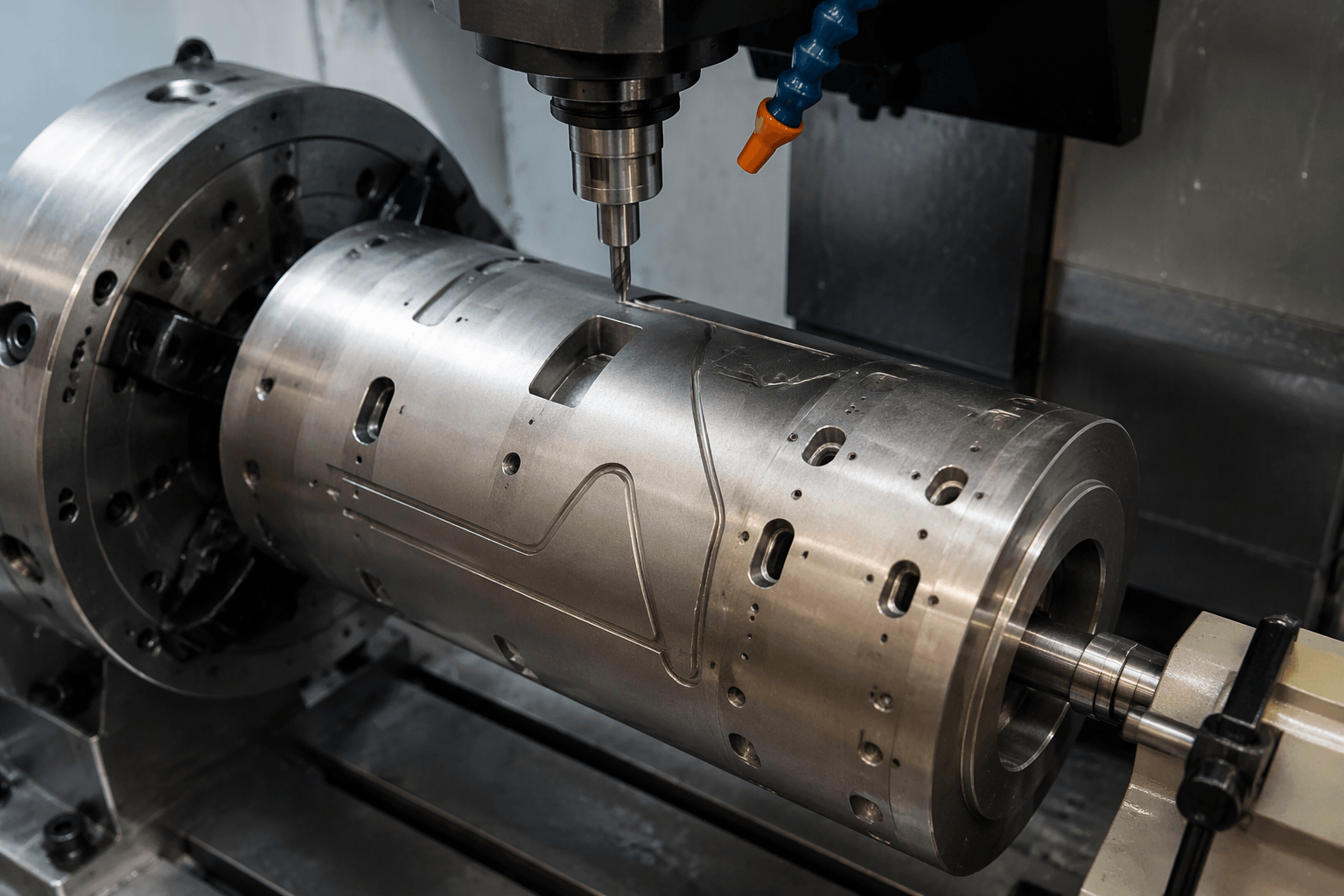
Hypothetical example: Consider a cylindrical shaft with a row of shallow pockets on several sides and a helical groove running around its surface. This is an illustrative geometry, not a customer project or a claim about a particular machine’s capabilities.
The separate pockets may be approachable with indexed positioning if each can be machined with the rotary axis held at a suitable angle. The setup would rotate the shaft to one orientation, hold it for that cut, then index to another orientation for the next pocket. The actual feasibility still depends on tool access, the pocket geometry, the workholding, and the machine’s usable travel.
The helical groove illustrates a different motion requirement. If its programmed path requires the tool to travel along the shaft while the shaft rotates during cutting, the operation needs coordinated rotary and linear motion. An indexed-only setup cannot create that same continuously coordinated path merely by stopping at successive angles. Whether a simultaneous setup can produce the feature depends on the supported toolpath, axis coordination, and physical setup.
For either feature, confirm the whole motion chain before choosing a configuration:
- Machine configuration: Identify the axes available for the operation, their arrangement, and whether installing or configuring the rotary unit changes access to a linear axis.
- Rotary hardware: Check how the unit is mounted and controlled, and whether its motion and usable setup suit the part. Do not assume an accessory fits a machine based on the “4th axis” label.
- Controller: Verify that the control supports the required positioning or coordinated axis motion in the intended configuration.
- CAM and postprocessor: Confirm that the CAM workflow can create the required toolpath and that the postprocessor outputs motion the target controller and machine can execute.
- Workholding and tool access: Check how the part is supported, which areas remain reachable, and whether the setup allows the planned cuts without interference.
These checks connect the part’s geometry to actual machine capability. A machine described as four-axis may suit indexed work but not the simultaneous motion a particular contour requires; another configuration may provide coordinated motion but still be unsuitable for a feature because of access or workholding. Evaluate the programmed operation, not just the axis count.
How four-axis machining differs from five-axis
A four-axis arrangement commonly combines three linear axes with one rotational axis. Five-axis machining typically adds another rotational degree of freedom, allowing a broader range of relative orientations between tool and workpiece. The exact axis names and which component moves vary by machine design.
The useful distinction is whether the required tool or workpiece orientations and programmed movements can be reached with the available axes. A part may need only indexed rotary access, coordinated rotary motion, or additional orientation from another rotational axis. Axis count alone does not establish accuracy, surface quality, or suitability; those depend on the complete machine, setup, tooling, programming, and part requirements.
Next step: check the part against the configuration
Start with the part geometry and list the features that must be cut, their orientations, and whether any toolpath requires rotation during cutting. Then compare those motions with the machine configuration, controller, CAM and postprocessor workflow, rotary hardware, and workholding specifications. This turns a general “4th-axis” claim into a capability check for the actual part. For readers looking for custom machined parts rather than equipment, see Custom CNC Machining From First Sample to Repeat Production.
Where RFQ Assumptions Create Cost and Production Risk
Many sheet metal fabrication problems begin before production starts. If drawings, tolerances, finish expectations, material grades, or assembly requirements are unclear, suppliers may quote based on different assumptions. That can make prices difficult to compare and may lead to rework, cosmetic rejection, assembly misalignment, or production delays later.
For OEM buyers, the goal is not simply to request the lowest price. The goal is to make sure each supplier is quoting the same manufacturing reality. Before confirming an order, clarify which dimensions are fit-critical, which surfaces are cosmetic, whether prototypes must match batch-production conditions, and how finished parts will be inspected.
Frequently Asked Questions
What 4th axis cnc details should buyers define before requesting a quote?
Buyers should define the functional requirement, drawing notes, critical dimensions, material or process expectations, and any inspection points related to 4th axis cnc. This helps suppliers quote the same manufacturing scope instead of making different assumptions.
How can RFQ details affect cost, fit, or lead time?
RFQ details can change tooling, forming, welding, finishing, inspection, or rework requirements. If buyers do not clarify it early, two supplier quotes may look comparable while covering different production risks.
Why should drawing requirements be reviewed before prototype approval?
drawing requirements may look acceptable on a single sample but become harder to control during batch production. Buyers should confirm whether the prototype reflects the same process, finish, and inspection conditions expected for production.
What inspection points matter most for 4th axis cnc projects?
Important inspection points usually include fit-critical dimensions, holes or mating areas, cosmetic surfaces, finish build-up, welded or formed features, and any dimensions that affect downstream assembly. These points should appear in the RFQ or drawing notes.
How can buyers reduce prototype approval risk before batch production?
Buyers can reduce risk by clarifying drawings, locking key material and finish assumptions, defining inspection timing, approving a representative sample, and confirming which dimensions or surfaces require tighter process control.
How can Yishang help review 4th axis cnc requirements?
Yishang can review drawings, RFQ notes, material requirements, tolerance expectations, finish details, samples, and assembly needs to identify unclear assumptions before quoting or batch production.