
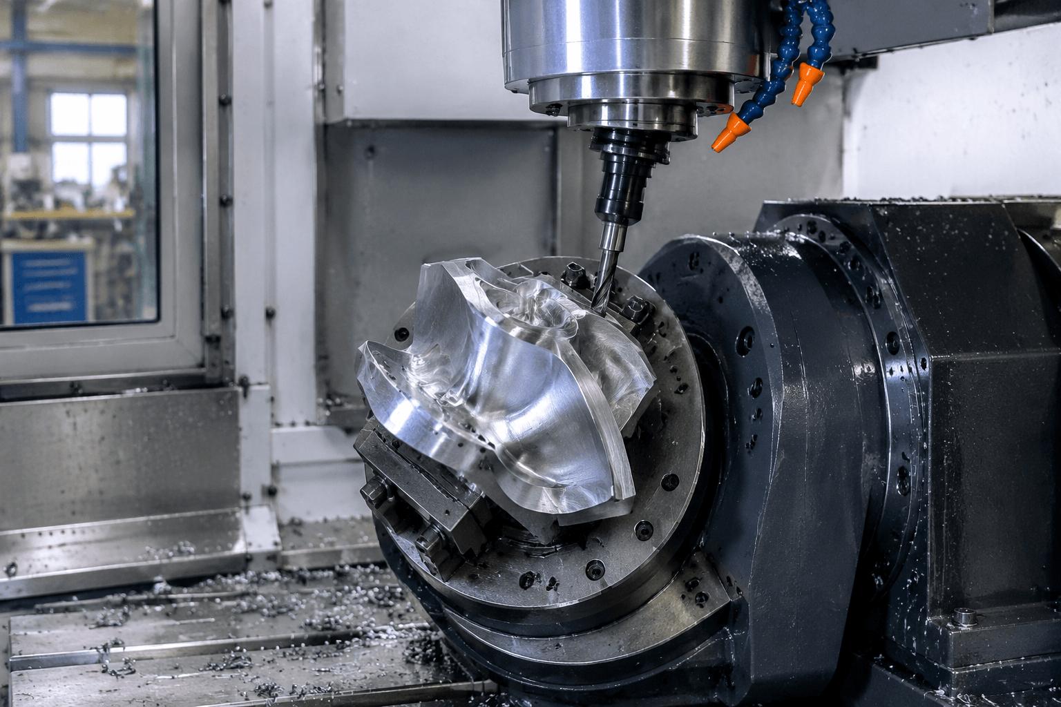
Five-axis machining is most relevant to industries whose parts contain complex surfaces, angled or obstructed features, or multiple critical faces that require controlled access. Aerospace-style components, medical equipment parts, tooling-related components, transportation equipment, energy hardware, and specialized machinery may all encounter these requirements. However, the industry name alone does not determine suitability. The part geometry, material, tolerances, inspection requirements, quantity, and assembly function determine whether five-axis machining is an appropriate manufacturing route.
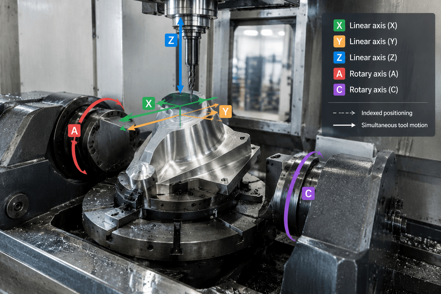
In practical terms, five-axis CNC machining is a subtractive process. A cutting tool removes material from a workpiece while the machine controls movement along the linear X, Y, and Z axes and two rotary axes. The exact arrangement of the rotary axes varies by machine configuration, so every five-axis machine should not be treated as identical. The important process question is whether the available combination of tool movement and workpiece orientation provides reliable access to the required features.
What Industries Use Five-Axis CNC Machining?
Five-axis machining can be useful wherever a component combines difficult access with a need to control relationships between several features. The following are application categories, not claims about a particular supplier’s production history.
Transportation and automotive equipment: housings, brackets, tooling-related components, and contoured structural parts may include angled faces, compound surfaces, or interfaces that are difficult to reach after repeated repositioning. The relevant question is whether the component’s geometry benefits from controlled access to several faces.
Medical and laboratory equipment: equipment components can include contoured housings, fluid paths, mounting interfaces, and small features arranged across multiple orientations. Five-axis access may be considered when the design cannot be addressed efficiently from one or two straightforward setups. The required material, surface condition, cleanability, and inspection approach still need to be assessed from the drawing.
Tooling and mold-related work: inserts, electrodes, fixtures, and other tooling-related components often contain sloped surfaces, deep cavities, compound curves, or features that must align with another tool component. A multi-axis approach may help position the cutting tool relative to those surfaces, although the final method depends on the tool geometry and required finish.
Industrial and energy equipment: equipment parts may combine structural surfaces, bores, ports, mounting faces, and access-limited areas. Five-axis machining is worth evaluating when these features require several controlled orientations and when the relationships between datums and mating surfaces are important.
Engineering prototypes and specialized machinery: a prototype can be a useful setting for reviewing whether the intended geometry is practical to manufacture. It can expose access, workholding, fit, or assembly issues before repeat production. A prototype does not automatically require five-axis machining; a simpler milling, turning, fabrication, or hybrid route may be more suitable.
For broader context on prototype-to-production planning, see Custom CNC Machining From First Sample to Repeat Production. The process decision should remain specific to the part rather than being inferred from the industry label.
Which Part Features Make Five-Axis Machining Useful?
The strongest reason to consider five-axis machining is usually access. A part may be difficult to produce efficiently or consistently when its important features face different directions, sit behind other surfaces, or follow compound curves.
Angled holes and ports may require the tool to approach the workpiece at a controlled angle. Depending on the geometry, a three-axis machine may address the feature after additional setups, while a five-axis process may provide another way to orient the tool or workpiece. The drawing still determines whether the approach is feasible and how the feature must be inspected.
Compound curves and contoured surfaces can require the cutter to maintain a suitable relationship to the surface as the tool travels. This can be relevant to aerodynamic-style forms, ergonomic housings, impellers, tooling surfaces, and other non-planar geometries. The presence of a curve alone does not prove that simultaneous five-axis cutting is necessary; the surface shape, cutter access, finish requirement, and available tooling all matter.
Deep features, undercuts, and obstructed faces can create interference between the tool holder, cutter, workpiece, and fixture. Reorienting the workpiece or tool may provide access that is difficult from a fixed direction. Workholding and collision avoidance remain part of the feasibility assessment.
Multiple faces with controlled feature relationships may benefit from fewer manual repositioning steps. Fewer repositioning operations can simplify access and reduce opportunities for setup-related variation, but this should not be stated as an automatic tolerance or cycle-time improvement. The datum scheme, workholding method, machine configuration, programming strategy, and inspection plan determine the actual result.
Indexed positioning versus simultaneous cutting
Five-axis machining does not always mean that all five axes move continuously during cutting. With indexed five-axis positioning, the machine rotates or reorients the workpiece or tool to a selected position, then performs a cutting operation. The part may use several orientations, but the cutting motion within each orientation can remain comparatively conventional.
With simultaneous five-axis cutting, the linear and rotary axes can move together while the tool follows a changing path across a surface or feature. This may be useful for certain compound surfaces, difficult tool approaches, or collision-avoidance requirements. It also introduces programming, verification, machine-kinematic, and inspection considerations. A complex part may therefore need indexed positioning, simultaneous motion, or a combination of both. The part geometry should decide which approach is appropriate.
How Does Five-Axis Machining Compare With Other Processes?
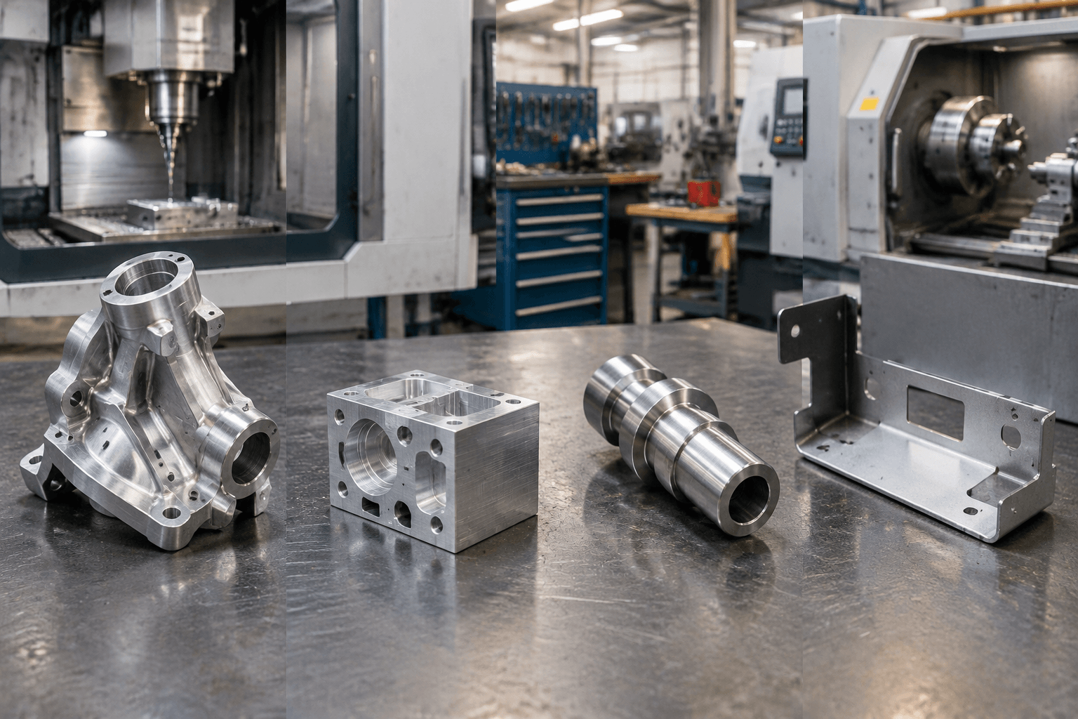
Five-axis machining is one process option within a larger manufacturing plan. It is not a replacement for turning, sheet metal fabrication, welding, finishing, assembly, or inspection. A geometry-based comparison is more useful than ranking one process as universally better.
| Part situation | Process that may be appropriate | Why the geometry matters |
|---|---|---|
| Complex surfaces, angled features, obstructed access, or several critical orientations | Five-axis CNC machining may be worth evaluating | Controlled tool or workpiece orientation can address features that are difficult to reach from a limited number of directions. |
| Flat or prismatic features that can be reached from a small number of setups | Three-axis or four-axis machining may be sufficient | A simpler machine path or indexed orientation may meet the drawing without the additional complexity of simultaneous five-axis work. |
| Primarily rotational geometry such as a shaft-like component | CNC turning may be the primary process | Turning is designed around rotational work, although milling or secondary operations may still be required for cross-holes, flats, or other non-rotational features. |
| Flat sheet, formed panels, bent enclosures, or cut-and-bent components | Sheet metal fabrication may be more suitable | Cutting, forming, bending, and joining sheet are different operations from removing material from a solid billet. |
| Frames or structures made from joined members | Welding and fabrication may be the primary route | The design may depend on formed or cut members and welded assembly rather than a monolithic machined part. |
| Surface appearance, corrosion protection, or a required coating | Finishing may follow the primary manufacturing process | Finishing changes the surface condition and is not interchangeable with the machining operation that creates the part geometry. |
| Parts that must be joined to other components | Assembly planning is required in addition to manufacturing | Mating dimensions, datums, clearances, fasteners, and access during assembly can influence the appropriate process. |
For example, a rotational component may begin with turning, a bent enclosure may begin with sheet metal fabrication, and a welded frame may require fabrication and welding. A contoured monolithic component with angled ports and several controlled faces may justify evaluating five-axis machining. These examples describe process logic, not fixed rules.
Industry-specific fabrication requirements can also differ substantially. The pages on automotive and transportation equipment and material handling and logistics equipment provide relevant industry context, but an industry page should not be treated as proof that a particular part requires five-axis machining.
What Project Information Determines Five-Axis Suitability?
A manufacturer needs the complete part requirement before recommending a process. The phrase five-axis industries may describe the search topic, but it is not enough information for a manufacturing decision.
Provide the part drawing and 3D model. The drawing should identify datums, critical dimensions, geometric relationships, thread details, notes, and revision status. The 3D model helps communicate compound surfaces and access conditions, while the drawing establishes the controlling requirements where the two differ.
Specify the material. Material behavior can affect cutting approach, workholding, tool selection, heat management, burr formation, and surface condition. The material grade or specification should be stated rather than inferred from the model or application name.
Identify critical tolerances and surfaces. Not every dimension has the same functional importance. Mark dimensions that affect mating parts, movement, sealing, alignment, load transfer, or assembly. Include surface-finish requirements and identify whether a surface is functional, cosmetic, or simply required to remove machining marks.
Define inspection expectations. Explain which features require documented inspection, what datum structure should be used, and whether inspection records are expected for a prototype or production quantity. Inspection is a separate quality activity; it does not become part of the five-axis cutting operation simply because the part was machined on a multi-axis machine.
State quantity and production status. A one-off prototype, an engineering sample, a small repeat batch, and ongoing production can lead to different decisions about programming, fixtures, workholding, process validation, and inspection. The most appropriate route depends on the total requirement rather than the machine type alone.
Explain assembly interfaces. Include mating-part drawings or interface details when available. A feature that appears acceptable in isolation may create a fit, clearance, alignment, or access problem when assembled. Prototype review can help identify those issues before repeat production, but the review criteria should be agreed in advance.
Material behavior, tool access, workholding, machine configuration, programming strategy, and inspection method should be considered together. A five-axis process may solve an access problem while introducing other planning requirements, and a simpler process may be entirely adequate when the geometry allows it.
What Outcomes Should Buyers Evaluate Beyond the Machine Type?
Buyers should evaluate whether the selected route supports the finished component and its assembly function. The machine label is only one part of that assessment.
Start with feature relationships and datum strategy. Ask how the important faces, holes, bores, and contours relate to the drawing datums. Then consider surface condition, including whether the result supports sealing, sliding, visual appearance, or contact with another part. Finally, connect the manufacturing plan to inspection and fit: which dimensions will be checked, how will the inspection reference the drawing, and which mating parts must be available for an assembly review?
For prototype work, the review should cover more than whether the part exists. It should consider access to the features, workholding marks, fit with mating parts, assembly sequence, surface condition, and any drawing requirement that could affect repeat production. These checks can inform a later process decision without assuming that the prototype method will be identical to the production method.
OEM and ODM teams can request a technical discussion using a part drawing or 3D model, material and finish requirements, critical tolerances, inspection expectations, estimated quantity, prototype or production status, and assembly or mating-part information. The purpose is to identify an appropriate manufacturing route, with five-axis machining considered alongside simpler machining, turning, fabrication, and other relevant processes rather than assumed in advance.
Frequently Asked Questions
What hole alignment details should buyers define before requesting a quote?
Buyers should define the functional requirement, drawing notes, critical dimensions, material or process expectations, and any inspection points related to hole alignment. This helps suppliers quote the same manufacturing scope instead of making different assumptions.
How can tolerance stack affect cost, fit, or lead time?
tolerance stack can change tooling, forming, welding, finishing, inspection, or rework requirements. If buyers do not clarify it early, two supplier quotes may look comparable while covering different production risks.
Why should mating parts be reviewed before prototype approval?
mating parts may look acceptable on a single sample but become harder to control during batch production. Buyers should confirm whether the prototype reflects the same process, finish, and inspection conditions expected for production.
What inspection points matter most for 5 axis industries projects?
Important inspection points usually include fit-critical dimensions, holes or mating areas, cosmetic surfaces, finish build-up, welded or formed features, and any dimensions that affect downstream assembly. These points should appear in the RFQ or drawing notes.
How can buyers reduce fit-up inspection risk before batch production?
Buyers can reduce risk by clarifying drawings, locking key material and finish assumptions, defining inspection timing, approving a representative sample, and confirming which dimensions or surfaces require tighter process control.
How can Yishang help review 5 axis industries requirements?
Yishang can review drawings, RFQ notes, material requirements, tolerance expectations, finish details, samples, and assembly needs to identify unclear assumptions before quoting or batch production.