
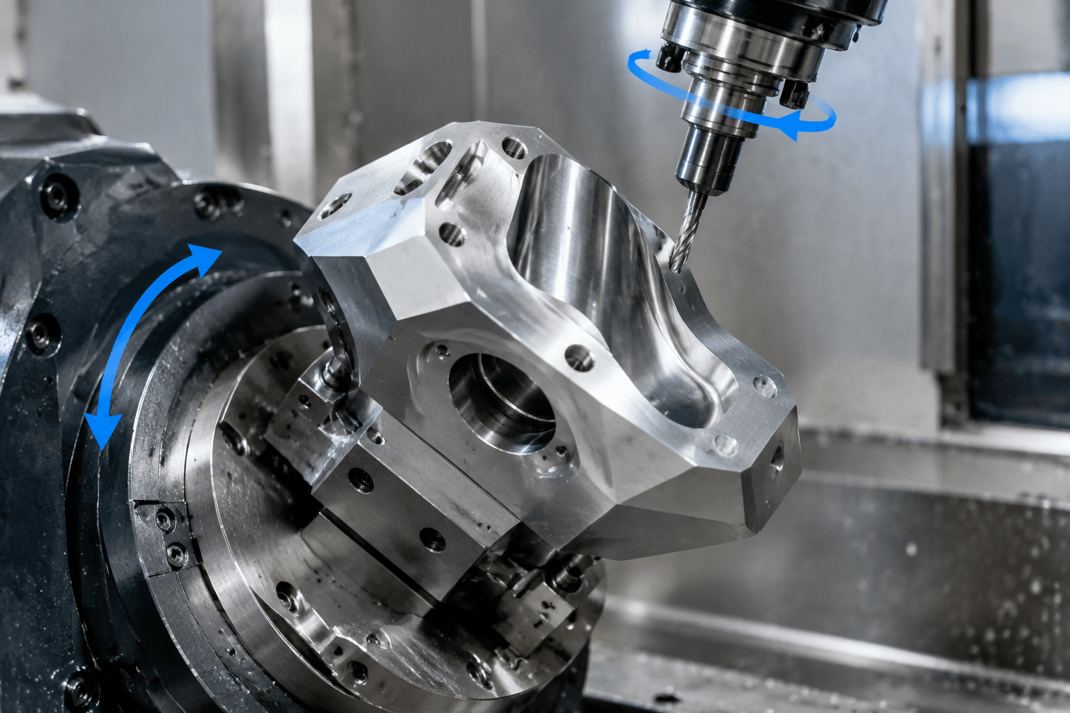
5 axis machining services use three linear axes and two rotary axes to machine features from different orientations. Indexed 3+2 machining holds the rotary axes stationary during each cut, while simultaneous five-axis machining coordinates linear and rotary motion during cutting; a provider may offer either or both.
Consider a hypothetical housing with angled holes, locating faces on several sides and a curved outer surface. Each feature raises a different question about cutter access, workholding and measurement. Buying the service means agreeing how those features will be produced and verified, with the operating mode confirmed for the actual geometry.
What does a five-axis machining service include?
A machining proposal should define the scope: manufacturing review, programming, workholding, cutting, deburring and agreed inspection. Material supply, outside finishing and documentation may also be included, but these deliverables need explicit agreement. The machine’s axis count alone does not establish what the order covers.
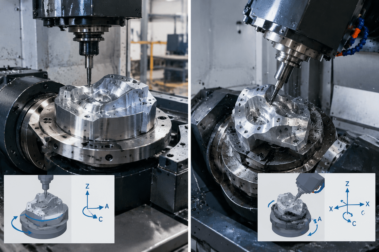
The three linear axes are X, Y and Z. The two rotary axes change the orientation of the tool relative to the workpiece through movement of the table, spindle head or both. Their labels depend on machine configuration; A, B and C designate rotation about X, Y and Z respectively.
Indexed 3+2 positioning can suit holes, pockets and faces that need different fixed approach angles. Simultaneous motion may help where tool orientation must change along a contoured surface. Both require suitable programming and clearance checks. The broader custom CNC machining scope provides a starting point for discussion, but five-axis availability and the proposed operating mode require separate confirmation.
One hypothetical housing: features, access and deliverables
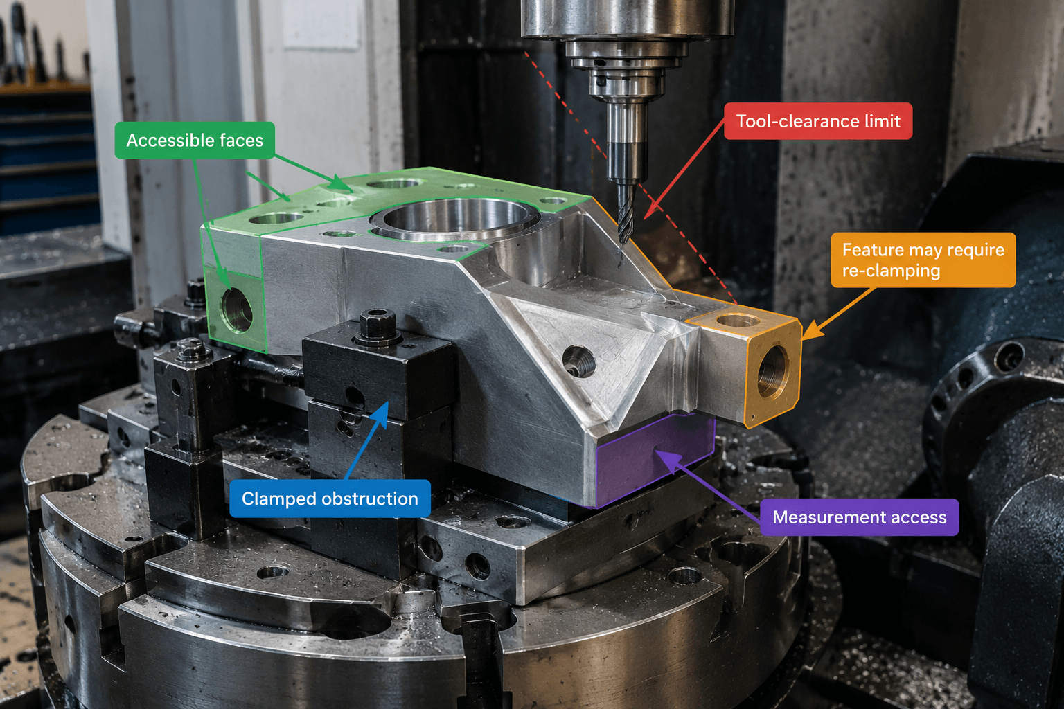
The following annotated example illustrates process decisions; it is not a completed customer project or a claim of supplier capability. Imagine a solid-machined housing with a mounting base, two angled ports, side locating faces and a sculpted cover surface.
Feature A: angled ports
Indexed positioning could align each port with the cutting tool, allowing drilling or milling along a fixed direction. The deliverable is the specified hole geometry and orientation relative to the drawing datums. Hole depth, tool length and clearance around the entry determine whether that approach is practical.
Feature B: related locating faces
Machining several locating faces while the housing remains clamped may reduce variation introduced by transferring it between fixtures. The drawing still needs to define their relationship, such as perpendicularity or position relative to a datum. Faces hidden beneath clamps may require another setup.
Feature C: curved cover surface
Simultaneous machining may allow the cutter to tilt as it follows the contour, helping maintain useful contact conditions or clear adjacent walls. Some contours remain suitable for three-axis milling. The surface shape, cutter geometry and required texture determine whether continuous orientation changes add value.
Feature D: underside mounting recess
A recess beneath the clamped base illustrates the remaining access problem. Rotary movement cannot make a fixture disappear. Re-clamping, different support locations or another operation may be necessary, with a plan for recovering the relevant datums.
Across all four features, feasibility depends on tool reach, holder clearance, fixture obstructions, machine travel and part rigidity. A long cutter may reach a feature but deflect excessively. A deep cavity or undercut still requires a viable tool path and suitable cutter geometry; five-axis motion alone does not make it machinable.
How material and specifications shape the finished result
Material grade and condition belong in the machining review because they influence cutting forces, heat, tool wear and dimensional stability. The following are general engineering considerations, not a verified supplier material list. Aluminum alloys can present chip-control, burr and thin-wall deflection challenges. Steel behavior varies with alloy and hardness. Titanium’s relatively low thermal conductivity can concentrate cutting heat near the tool, making engagement and tool condition especially consequential.
Stock condition also matters. Residual stress in plate, bar or other starting stock can cause movement as material is removed. Heat treatment and the sequence of roughing and finishing may affect the final dimensions. A rigid external block and a thin-walled housing made from the same alloy therefore need different process decisions.
Dimensional tolerance, geometric requirements and surface texture describe different aspects of acceptance. A hole diameter does not establish its position relative to a mounting face. A smooth-looking surface does not prove flatness, and a compliant profile does not establish a specified texture. Identify the characteristics that control assembly and function, together with their datum references.
These requirements interact: a slender tool may provide access but compromise size control or leave vibration marks. Workholding can distort a thin wall during cutting and measurement. Anodizing, plating or another finishing operation is separate from producing an as-machined surface and may affect dimensions. The process plan should account for the required final condition.
Setup choices affect feature relationships and production time
For the hypothetical housing, cutting the angled ports and side locating faces in one clamping could preserve their relationship without a fixture transfer. Finishing the underside may still require turning the component over. That transfer needs a locating method that references appropriate surfaces without damaging them or distorting the part.
Fewer setups can reduce transfer-related variation, but machine accuracy, tool deflection, thermal effects and clamping remain relevant. The useful comparison is whether each proposed route can meet the drawing with suitable access and verification.
| Possible route | Where it may fit | Planning consideration |
|---|---|---|
| Three-axis milling | Accessible faces and pockets | Additional orientations may require fixtures or transfers. |
| Indexed 3+2 machining | Features needing several fixed approach angles | Check tool clearance at each orientation and access beneath clamps. |
| Simultaneous five-axis machining | Contours benefiting from changing tool orientation | Confirm coordinated motion, collision clearance and surface verification. |
Predominantly rotational geometry may be better suited to turning, potentially followed by milling. Five-axis milling does not inherently include turning. Similarly, a straightforward part may meet every requirement through three-axis machining with practical workholding.
Production time includes programming, fixture preparation, cutting, tool changes, inspection and any outside processing. Reducing cutting time does not automatically shorten delivery. Prototype and repeat quantities can justify different fixture investments, so quantity should inform the proposed route.
Inspection defines acceptance and supports repeat orders
Verification should connect directly to specified drawing characteristics. For the example housing, that could mean checking port orientation, locating-face relationships and the cover profile. Measurement access needs review alongside cutting access: a machined feature may be difficult to probe or inspect once surrounding geometry is complete.
A statement that parts are inspected is less specific than an agreed report identifying characteristics, datum references, measurement methods and sampling scope. Confirm available methods and documentation before ordering. Inspection verifies the result; cutting capability alone does not establish a measurement capability.
Repeat production benefits from controlled drawing revisions, material identification, approved setup information, tool references and inspection records. Together, these provide a basis for reproducing the process and assessing changes. Stock variation, tool wear and production conditions still require control; a previous successful batch does not guarantee identical outcomes or delivery times.
For a component-specific discussion with Yishang, share a CAD model or drawing if available, material grade and condition, critical features, surface requirements and intended quantity. Use the CNC machining service page to begin defining the machining and verification scope. Confirm five-axis service availability and the appropriate operating mode before committing to a process or order.