
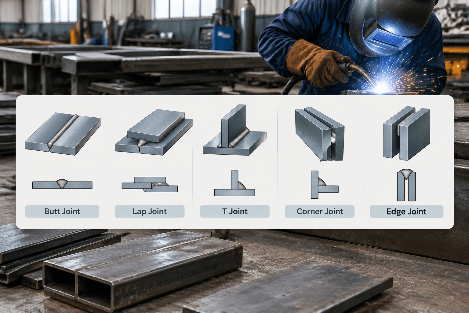
The 5 basic weld joints are butt, lap, T, corner, and edge joints. They describe how two members are positioned relative to each other before welding. They do not identify the welding process, weld type, or welding position.
The configuration affects access, fit-up, edge preparation, penetration, distortion, and load transfer. The appropriate choice depends on the material, thickness, service conditions, available access, and applicable design or fabrication requirements.
Butt       Lap          T           Corner       Edge
A | B      A overlaps B A meets B   A meets B    A and B edges
[A][B]     [A]          [A]         [A]          [A][B]
                        | B         | B          parallel/aligned
The five basic weld joints at a glance
A weld joint is the arrangement formed where two or more members meet. The five basic welding joint types are defined by member geometry rather than by the equipment, shielding gas, electrode, or consumable used to make the weld.
| Joint | Member relationship | Primary design question |
|---|---|---|
| Butt | Two members meet end to end, usually in the same plane. | Can the edges and root be prepared and accessed adequately? |
| Lap | One member overlaps another. | Will the overlap provide the required connection without creating access, drainage, or cleaning problems? |
| T | One member intersects another at approximately 90 degrees. | Which side or sides can be welded, and how will the load reach the connection? |
| Corner | Two members meet to form an outside or inside corner. | Can the corner be fitted, welded, and kept dimensionally stable? |
| Edge | Adjacent edges are aligned or brought together and joined along the edge region. | Do the edges provide enough material and access for the intended weld and service condition? |
These configurations should not be confused with welding processes such as MIG, TIG, stick, flux-cored, or submerged arc welding. A process describes how heat and filler, if used, create the weld. A welding position describes the orientation during welding, such as flat, horizontal, vertical, or overhead. A weld type, such as a fillet or groove weld, describes the form of the deposited weld. A weld symbol communicates selected information on a drawing; it does not replace the underlying joint geometry.
Butt joints: end-to-end alignment and root preparation
A butt joint joins two pieces end to end, normally with their principal surfaces aligned. It may be selected when the design calls for a relatively continuous surface or a direct connection between sections. The joint can use square edges, prepared edges, backing, or an open root, depending on thickness, material, access, penetration requirements, and the specified weld detail.
Square-edge butt joint       Prepared-groove butt joint
Member A | Member B          Member A \    / Member B
          root region                    \  /
                                          root region
Thin sheet may sometimes be joined with square edges, while thicker material may need a bevel, V, J, or U preparation to make the weld region accessible. Thickness alone does not determine the preparation. Alloy, joint restraint, access, required penetration, distortion control, and the governing drawing or procedure also matter.
Fit-up is important because misalignment or an inconsistent root condition can change the heat and filler required. When welding is possible from only one side, the design may need to consider backing or an open-root arrangement. Backing can support the root during welding, but its suitability depends on the finished part, service environment, access, and project requirements. An open root may be appropriate for one procedure and unsuitable for another.
Butt joints can be used for panels, plates, tubing, and fabricated sections, but they may require more edge preparation than an overlapping arrangement. Long seams can also be sensitive to shrinkage and distortion. Joint length, restraint, welding sequence, and required final dimensions should be reviewed together.
Lap and T joints: overlap versus intersection
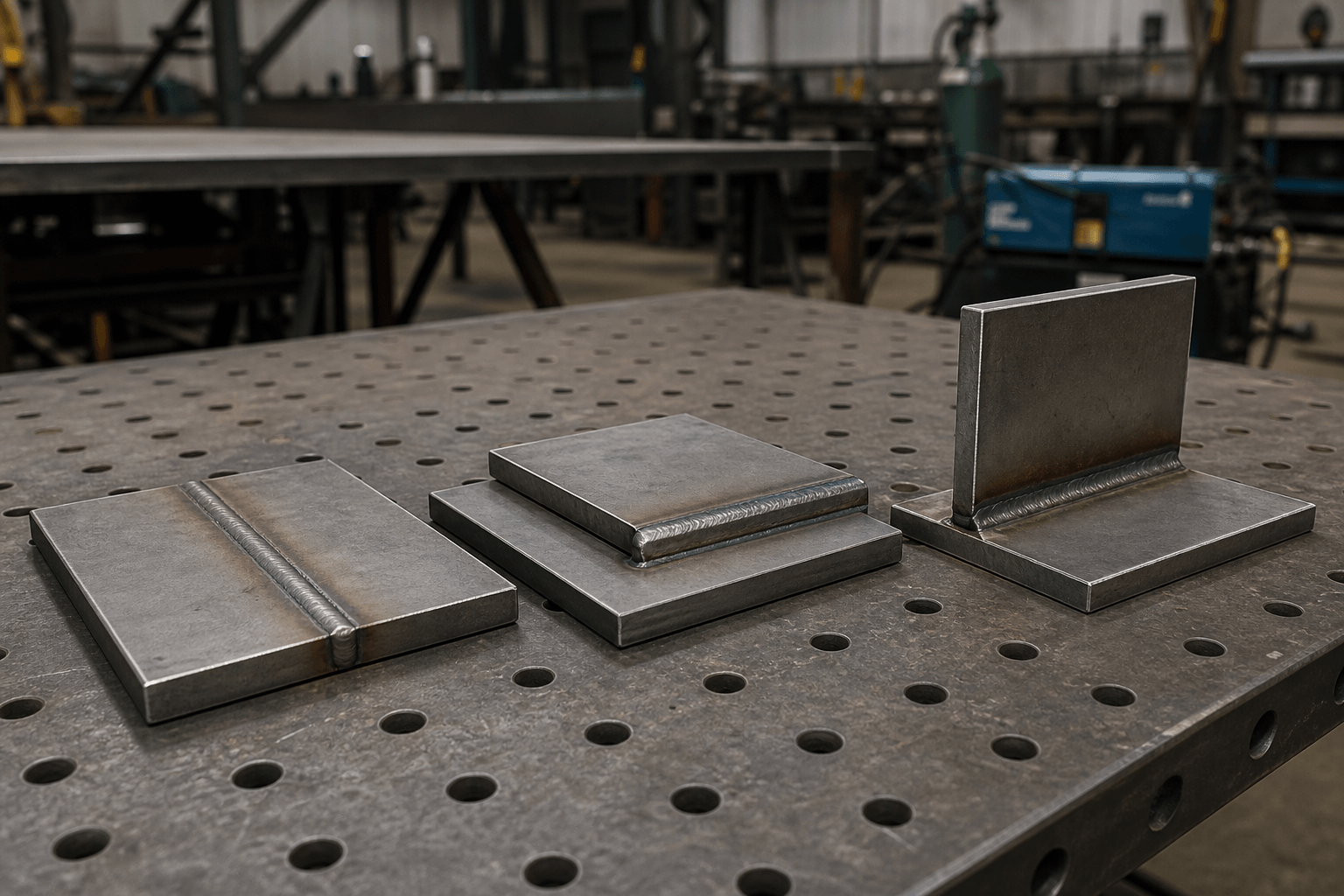
Lap and T joints are common in brackets, frames, supports, and sheet-metal assemblies, but their member relationships are different. A lap joint uses overlap. A T joint uses the intersection of one member with the face or edge of another.
| Point of comparison | Lap joint | T joint |
|---|---|---|
| Geometry | One member extends across and overlaps another. | One member meets the face or edge of another at approximately 90 degrees. |
| Access | Welds may be placed along one or both accessible overlap edges, depending on the design. | Access may be available from one side of the intersecting member or from both sides. |
| Preparation | Edges may need little preparation, but overlap, contact surfaces, and drainage paths still require control. | Edges may be square or prepared according to thickness, penetration needs, and the selected weld detail. |
| Load review | Load transfer depends on overlap, weld location, member stiffness, and force direction. | Load direction and the loaded side matter; a one-sided connection can behave differently from a two-sided arrangement. |
| Typical context | Overlapping sheet, straps, tabs, covers, and layered components. | Frames, brackets, ribs, webs, supports, and panel-to-frame intersections. |
A lap joint can help locate one member over another, but the overlap may affect cleaning, coating access, drainage, and overall thickness. A T joint can connect a web, rib, bracket, or base plate at an intersection. Neither configuration is inherently stronger in every application. The review should consider tension, shear, bending, vibration, impact, restraint, and the intended load path.
Corner and edge joints in sheet assemblies
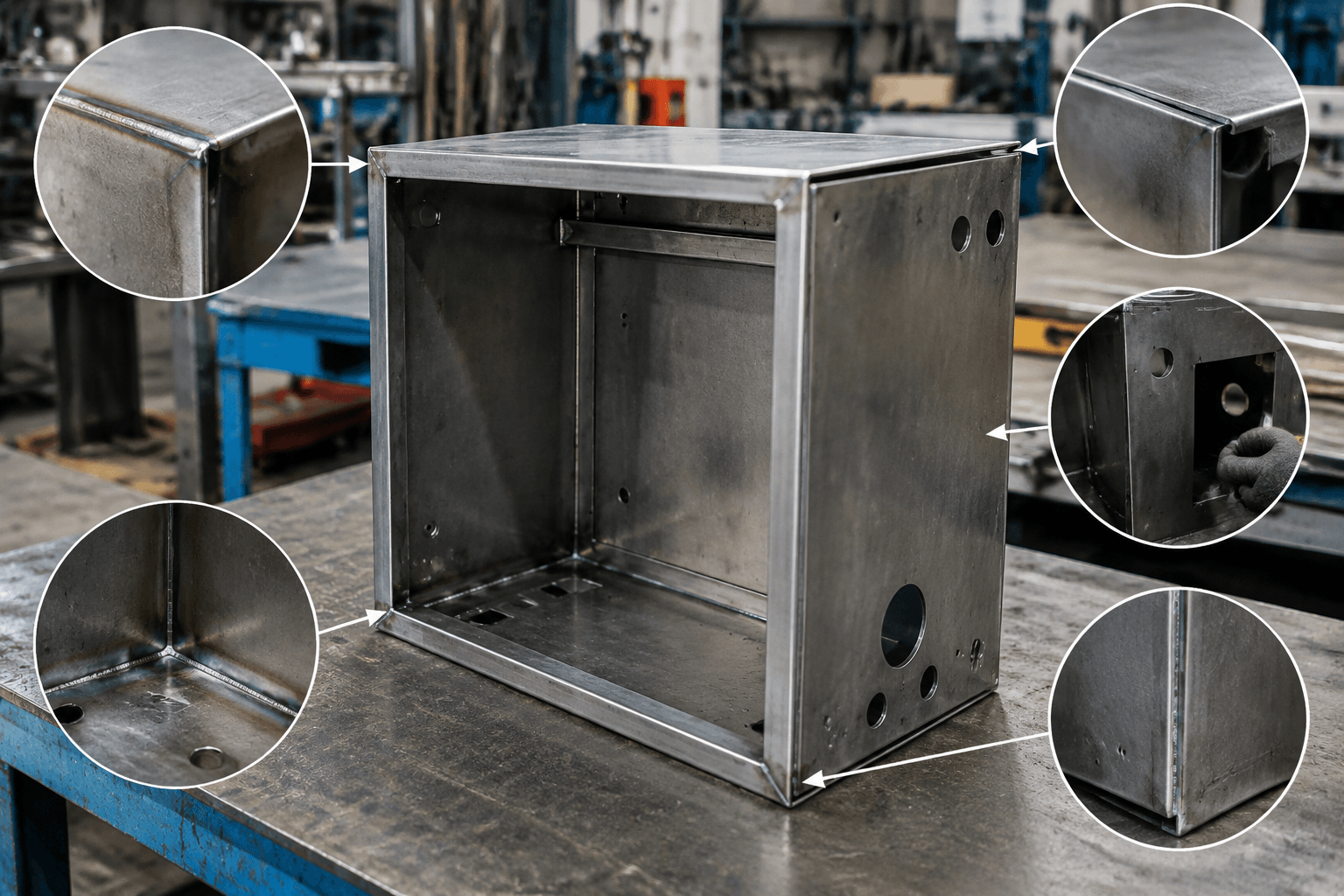
A corner joint joins members that meet to form a corner. The members may create an open corner, a closed corner, or an aligned corner in which their edges meet to define an inside or outside boundary. These arrangements are related but not identical: the weld path, visible surface, heat concentration, and fit-up condition can change between them.
Corner joint: members meet at a corner    Edge joint: aligned edges meet
      Member A                               Member A | Member B
      [       ]                                      [A][B]
          | Member B                                 || joined edge region
          |                                           ||
A corner joint is used when panels, plates, or sections form an enclosure, tray, frame, cover, or similar boundary. The weld may be accessible from the outside, inside, or both. An outside corner may have appearance requirements, while an inside corner can restrict tool or inspection access. Fit-up matters because mismatch can change the corner profile and increase distortion.
An edge joint is more specific than two edges merely touching. It refers to members whose adjacent edges are aligned or brought together so the connection is made along the edge region, often with the members lying in parallel or closely related planes. It is distinct from a corner joint, where the members meet to form an angular boundary. Edge joints can suit some sheet assemblies or narrow flanges when the edge geometry and material thickness provide enough section for the intended weld.
Thin material is particularly sensitive to heat and movement, so edge and corner details may require controlled fit-up, sequence, restraint, or a suitable edge preparation. The joint should be selected from the part geometry and service requirements rather than from the appearance of the touching edges alone.
How to select a joint configuration for a real part
Joint selection is a design decision shared by the part designer, welding engineer, and fabricator. This matrix is a starting point for review, not a universal welding procedure.
| Design input | What to examine | Why it changes the decision |
|---|---|---|
| Material and thickness | Alloy, thickness variation, edge condition, and heat sensitivity. | These influence edge preparation, heat control, penetration needs, and distortion risk. |
| Access | Whether the joint can be reached from one side or both sides. | Access affects weld placement, root support, inspection, and whether backing or an open root can be considered. |
| Loading | Direction of tension, shear, bending, vibration, or impact. | The load path should match the intended connection detail; the same geometry can behave differently under different loading. |
| Fit-up and sequence | Assembly order, clamping, tack sequence, weld sequence, and allowable movement. | Uneven or restrained heating can pull panels and frames out of alignment. |
| Appearance and service | Visible surfaces, drainage, cleaning, coating, sealing, and environmental exposure. | Overlap, corners, backing, and accessible weld surfaces can affect the finished part. |
| Production requirements | Part quantity, repeatability, handling, automation, and inspection access. | A detail suitable for a prototype may require a different preparation or sequence for repeat production. |
Before releasing a drawing, show the joint location clearly and identify any critical weld type, side, appearance, backing, or inspection requirement. Final dimensions, acceptance requirements, and procedure details should come from the applicable design documentation, welding procedure, specification, or project standard.
For a technical design discussion, provide the part drawing or sketch, material and thickness, expected load or service conditions, the sides available for welding, and any appearance, backing, or inspection requirements. Those inputs allow the fabrication implications of the selected joint configuration to be reviewed without assuming a final detail before the design is examined.
Frequently Asked Questions
What 5 basic weld joints details should buyers define before requesting a quote?
Buyers should define the functional requirement, drawing notes, critical dimensions, material or process expectations, and any inspection points related to 5 basic weld joints. This helps suppliers quote the same manufacturing scope instead of making different assumptions.
How can RFQ details affect cost, fit, or lead time?
RFQ details can change tooling, forming, welding, finishing, inspection, or rework requirements. If buyers do not clarify it early, two supplier quotes may look comparable while covering different production risks.
Why should drawing requirements be reviewed before prototype approval?
drawing requirements may look acceptable on a single sample but become harder to control during batch production. Buyers should confirm whether the prototype reflects the same process, finish, and inspection conditions expected for production.
What inspection points matter most for 5 basic weld joints projects?
Important inspection points usually include fit-critical dimensions, holes or mating areas, cosmetic surfaces, finish build-up, welded or formed features, and any dimensions that affect downstream assembly. These points should appear in the RFQ or drawing notes.
How can buyers reduce prototype approval risk before batch production?
Buyers can reduce risk by clarifying drawings, locking key material and finish assumptions, defining inspection timing, approving a representative sample, and confirming which dimensions or surfaces require tighter process control.
How can Yishang help review 5 basic weld joints requirements?
Yishang can review drawings, RFQ notes, material requirements, tolerance expectations, finish details, samples, and assembly needs to identify unclear assumptions before quoting or batch production.