
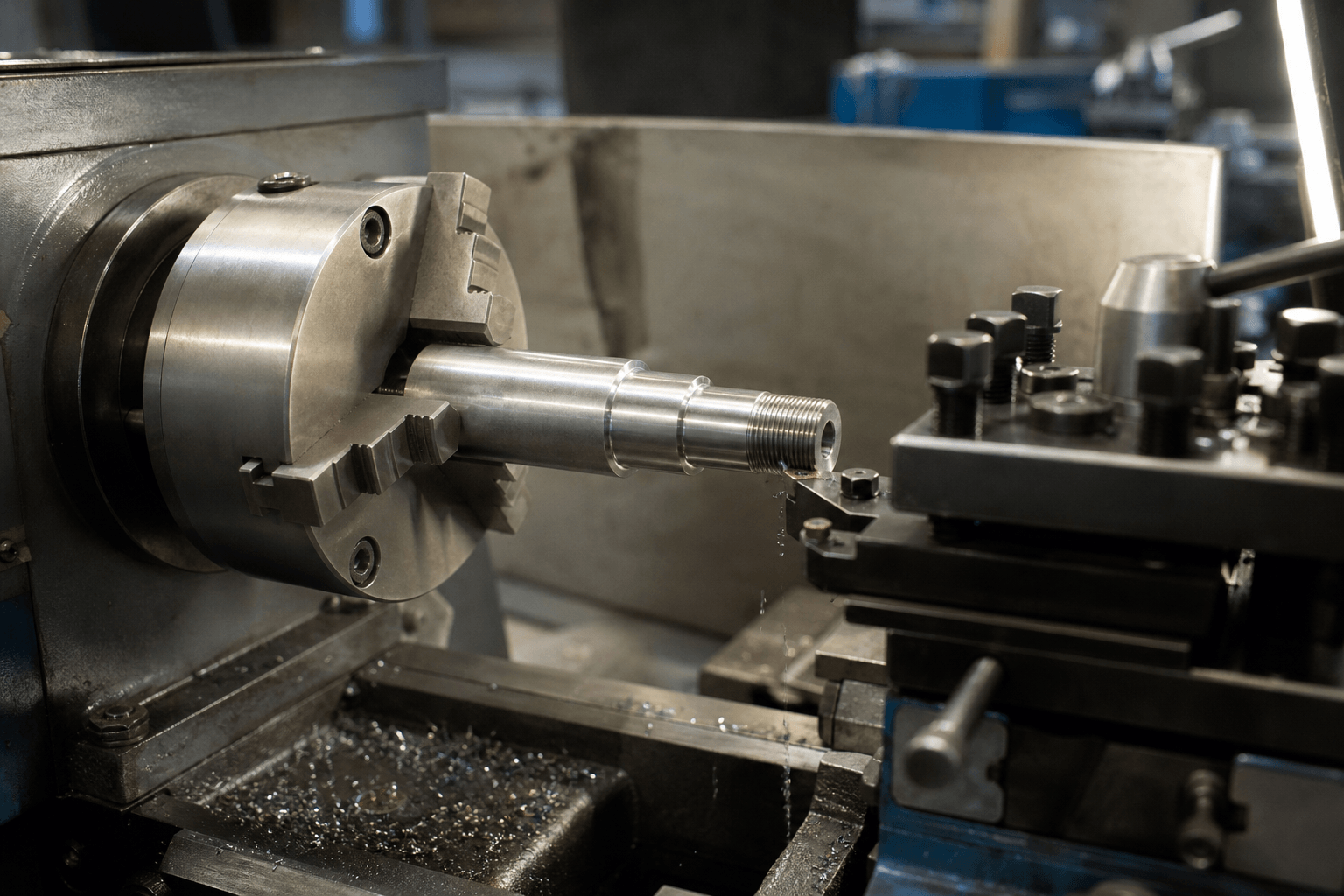
A lathe machine is commonly used for five operations: turning, facing, boring, threading, and parting or grooving. It rotates a workpiece while a cutting tool removes material to form cylindrical surfaces, flat ends, internal features, threads, or narrow cuts.
The five uses are: turning reduces or shapes an outside diameter; facing makes a flat end; boring enlarges or corrects an existing hole; threading forms internal or external screw threads; and parting or grooving separates a piece or cuts a narrow recess.
The table below compares the tool’s movement, the material removed, the resulting feature, and a typical workpiece situation.
| Lathe use | Tool movement | Material removed and result | Typical situation |
|---|---|---|---|
| Turning | Moves parallel to the workpiece axis | Removes material from the outside to reduce or shape a cylindrical diameter | Shaping a shaft or stepped cylindrical part |
| Facing | Moves across the workpiece end, toward or away from the axis | Removes material from the end to create a flat face | Squaring the end of a shaft or establishing an end reference |
| Boring | Moves an internal cutting tool along the axis inside an existing hole | Removes material from the hole wall to enlarge or correct its internal diameter | Adjusting an existing bore in a hub or sleeve |
| Threading | Moves a thread-cutting tool along the axis in a controlled relationship with spindle rotation | Removes material in a helical path to form an internal or external screw thread | Making a threaded end on a cylindrical component |
| Parting or grooving | Moves a narrow tool radially into the workpiece | Removes a narrow band of material to make a groove or, with a parting cut, separate a section | Cutting a relief groove or separating a finished component from stock |
How rotation and tool movement shape the cut
The spindle turns the workpiece, which is commonly held in a chuck. The cutting tool is secured in a tool post, and the carriage or cross-slide controls its position. In conventional operations, the workpiece supplies the rotating motion while the tool advances in a controlled direction. A lathe’s feed controls and drive arrangement govern how those motions are coordinated; the exact controls differ by machine.
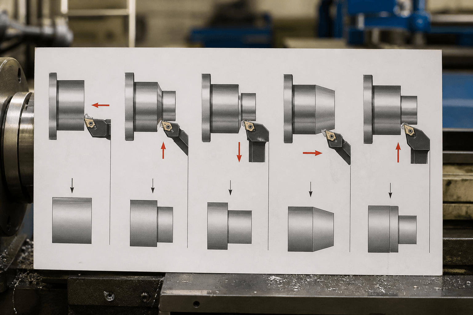
In turning, the tool travels along the axis while cutting the outer surface. In facing, it crosses the end face. A boring bar enters an existing hole and cuts its inside wall. Threading requires the tool’s axial travel to stay synchronized with spindle rotation so the cut follows a consistent helix. Parting and grooving use a narrow tool that advances toward the centerline. These paths explain why a lathe is most suited to features centered on a rotating axis.
Spindle speed affects how quickly the workpiece surface passes the cutting edge. Feed rate describes the tool’s advance relative to the rotating work. Together with tool geometry and the depth of cut, these settings influence material removal, surface finish, heat, tool wear, and the ability to control dimensions. Faster is not automatically better: an unsuitable combination can increase heat or vibration, damage the cutting edge, or make the finish less consistent.
Appropriate cutting conditions depend on the workpiece material, its diameter, the tool material and shape, the rigidity of the setup, and the operation being performed. A large-diameter workpiece has a different surface speed at a given spindle speed than a small one. A slender part may flex under cutting force, while a long unsupported part can vibrate. Use the machine maker’s guidance and suitable process references to select settings; there is no single speed or feed that applies to every lathe job.
Matching each operation to a part feature
Turning suits outside cylindrical surfaces. A shaft may need a reduced section, a stepped diameter, or a cylindrical surface brought to a specified shape. The tool moves parallel to the axis and removes material from the outside. Turning is most useful when the feature is rotationally symmetric and can be held and supported securely.
Facing establishes an end surface. A tool that crosses the end of a rotating bar removes material from that end, producing a flat face. This can prepare a reference surface or bring a part to its required length. Facing does not make a non-round profile; that geometry may call for a different process.
Boring works on a hole that already exists. A drill can create an initial hole, but boring uses a cutting tool to remove material from the internal wall and adjust the hole’s size or alignment. It is appropriate for an existing bore in a sleeve, hub, or similar part when the setup can hold the component and the boring tool can reach the required surface. Boring is not the same as drilling: drilling creates a hole, while boring cuts and adjusts an existing one.
Threading forms a screw interface. A lathe can cut external threads on a shaft or internal threads in a suitable bore, using a tool path synchronized to spindle rotation. The required thread form and fit come from the part drawing or applicable design specification. Do not assume that a general turning tool or an unsynchronized manual feed will produce the required thread.
Parting and grooving create narrow cuts. A grooving tool cuts a recess, such as a relief feature near a shoulder. A parting tool advances deeper until it separates a section from the stock. These cuts can place substantial demands on tool clearance, rigidity, chip control, and workpiece support, so the setup and tooling must suit the operation.
Think of a stepped shaft that needs a shaped outside diameter, a flat end, and a threaded interface: turning, facing, and threading may all be relevant. A sleeve with a pre-existing hole may call for boring instead. A narrow relief near a shoulder may call for grooving. By contrast, a new hole may be drilled, and a slot, pocket, or other non-round feature may be better made by milling. A drawing or 3D model, material, approximate dimensions, critical features, quantity, and finish requirements help clarify the appropriate manufacturing route. For a technical process review, provide the part drawing or 3D model, material, approximate dimensions, required operations, critical features, expected quantity, and finish requirements.
Selecting a lathe and preparing the setup
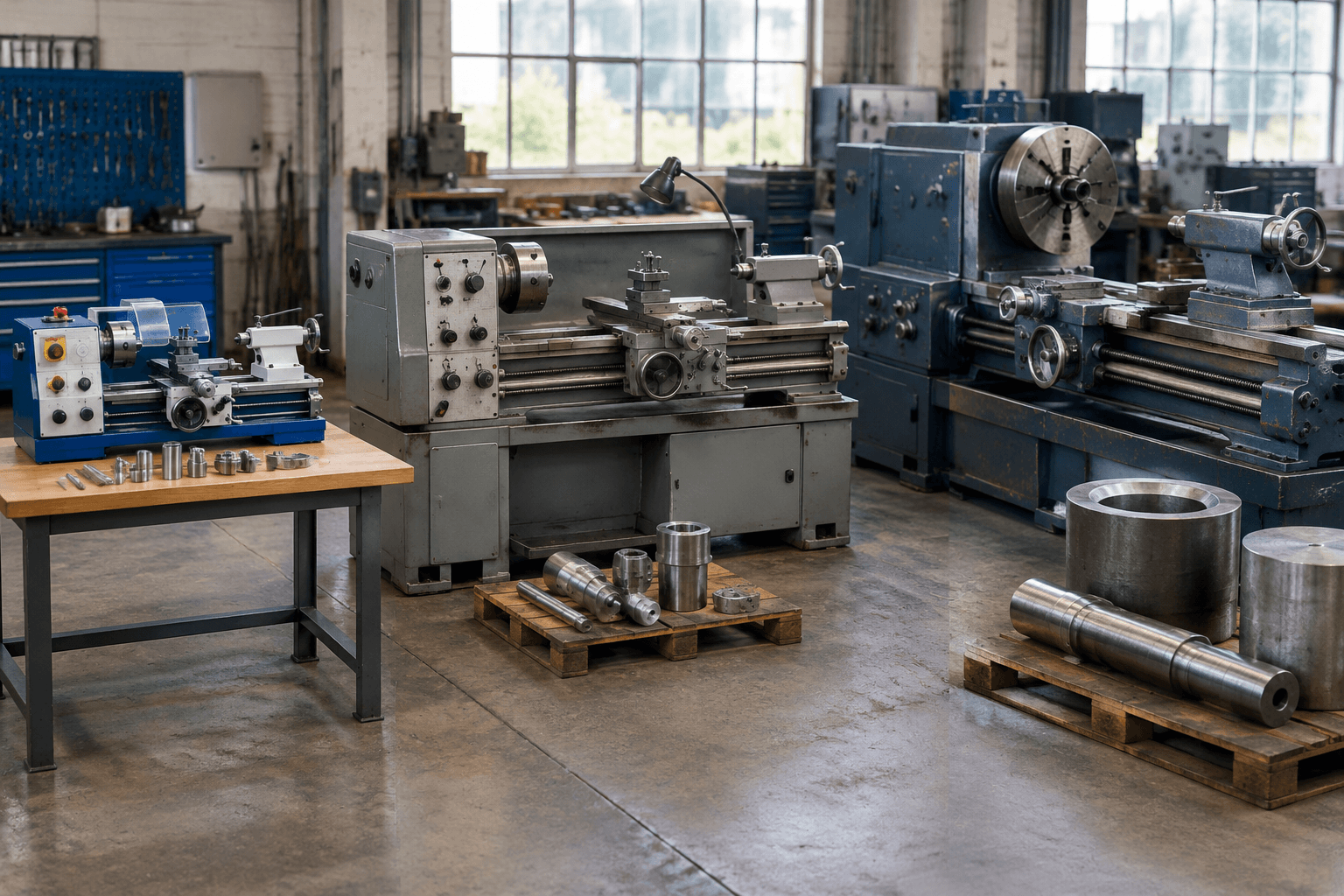
Choose a machine around the actual workpiece and workload, not just the operation name. Consider the maximum diameter and length required, part weight, how the part will be supported, cutting forces, expected duration of use, and production demand. Check the machine’s documentation for capacity and operating limits instead of inferring them from its general category.
| Machine category | Workpiece considerations | Workload considerations | Selection checks |
|---|---|---|---|
| Bench-top | Generally suited to smaller, lighter work that fits its documented capacity | Appropriate for lighter tasks; do not assume it can handle heavy, long, or continuous work | Available chucking and support, speed and feed control, tooling compatibility, and secure mounting |
| Universal | Offers a more adaptable setup for varied work within the machine’s stated limits | Consider the range of operations and how often the machine will run | Usable work envelope, workholding options, feed arrangements, and compatible tools |
| Heavy-duty | More appropriate to evaluate for heavier, larger-diameter, or longer workpieces | Consider sustained workload, rigidity, and production needs | Documented capacity, workpiece support, handling requirements, and suitable cutting equipment |
These categories are broad descriptions, not guarantees of capacity. A universal lathe is not automatically suitable for every part, and a heavy-duty machine is not necessarily the right choice for small or occasional jobs. The relevant manufacturer specifications, shop space, available handling equipment, operator training, and required process control all matter.
Before cutting, confirm that the workpiece is securely held in the chuck and that the setup is suitable for its size and shape. Check tool position and clearance through the intended travel, and ensure that the workpiece is supported where the operation requires it. Select a tool suited to the workpiece material and cut. Keep guards in place and follow the machine manufacturer’s operating instructions and applicable safety training. Do not treat a general guide as a substitute for either.
When Another Process Fits Better
A lathe is strongest when the required features are rotationally symmetric or share a common axis. It can produce outside and inside cylindrical surfaces, flat ends, threads, and grooves when the part can be held and the tool can reach the cut. Workholding and rigidity can restrict what is practical, particularly with long, thin, heavy, or irregularly shaped workpieces.
Slots, pockets, complex prismatic shapes, and many off-center features are often better suited to milling or another process. Some parts need multiple operations on different machines. Final process suitability depends on the drawing, material, geometry, workholding, and how the finished features must be verified.
Useful rule: consider a lathe when the feature is centered on a rotating axis and can be held securely; consider another process when the geometry is non-round, off-center, or inaccessible to the lathe tool. Confirm the route against the actual part requirements before selecting equipment or planning production.
Frequently Asked Questions
Where can I use a lathe machine, and what parts are suitable?
A lathe is suitable for parts with cylindrical or other rotationally symmetric features, such as shafts, sleeves, and hubs. Whether a particular part fits depends on its dimensions, weight, material, geometry, workholding, and the machine’s documented limits.
What is the difference between turning, facing, boring, threading, and parting?
Turning cuts an outside diameter, facing cuts an end surface, boring enlarges or corrects an existing hole, threading forms a helical screw feature, and parting or grooving cuts a narrow recess or separates a section. Each uses a different tool path and produces a different feature.
How do I choose between a bench-top, universal, and heavy-duty lathe?
Compare the workpiece’s diameter, length, weight, required support, and cutting demands with the capacity stated by the machine manufacturer. Also consider workload duration, production demand, speed and feed control, tooling, available space, and handling requirements.
What tools and setup considerations are needed for basic metal-lathe operations?
The cutting tool must match the operation and workpiece material, and the part must be held securely with adequate support. Check tool clearance, speed and feed guidance, and guarding before operation. Follow the machine manual and formal safety training for the specific equipment.