
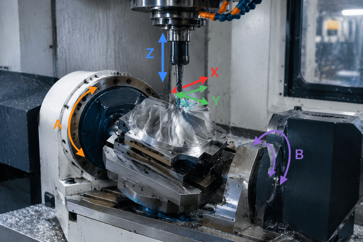
5th axis machining adds two rotational movements to the three linear movements of a CNC machine, letting the tool and workpiece change orientation relative to one another. The key distinction is whether those rotations position the part before cutting, as in indexed 3+2 machining, or continue moving during cutting, as in simultaneous 5-axis machining. That choice affects access, programming, setup planning, and the features a process can produce reliably.
In practical terms: 5th axis machining uses X, Y, and Z linear motion plus two rotational axes to orient a cutting tool relative to a workpiece. It can help reach angled and compound geometry, but the suitable method depends on the part, machine configuration, workholding, material, and inspection plan.
It is a CNC machining approach, not a synonym for every process that happens to use five or more axes. Understanding its operating modes is more useful than treating “5-axis” as a general promise of access or accuracy.
How 5th Axis Machining Works
The three linear axes describe straight-line movement: X and Y generally move across the machine’s working plane, while Z moves along the tool’s approach direction. Two additional axes rotate around axes in space. They are commonly labeled A, B, or C according to the axis each rotation is around, but the exact labels and arrangement depend on the machine.
Rotational movement can come from a tilting or swiveling table, a rotary table, a tilting spindle or head, or a combination. In a table-based configuration, the workpiece changes orientation beneath a comparatively fixed spindle. In a head-based configuration, the cutting tool tilts toward the workpiece. Some machines divide the two rotations between the head and table. Consequently, the same part program may involve different physical motions on different machine designs.
Changing orientation lets a cutting tool approach a feature from a direction that a fixed vertical tool cannot reach easily. It can also help maintain a more suitable relationship between the tool and a sloped or curved surface. Reach is still limited by the machine’s travel, rotary envelope, fixture, tool length, and collision clearance; five axes do not provide access to every feature from every direction.
Indexed 3+2 and simultaneous 5-axis cutting
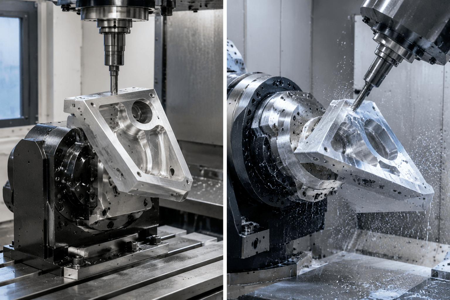
The terms describe different ways to use the rotational axes. In indexed machining, the machine rotates the workpiece or tool to a selected position, locks or holds that orientation, and then cuts using the linear axes. Simultaneous machining coordinates the linear and rotational axes while the cutter is engaged. A program can combine both approaches where appropriate.
| Approach | How motion works | Common fit | Planning focus |
|---|---|---|---|
| Indexed 3+2 | Two rotary axes position the part or tool; cutting then proceeds at a fixed orientation, usually with X, Y, and Z motion. | Angled faces, holes on different planes, and features reachable from several fixed orientations. | Orientation choices, fixture clearance, and maintaining references between positions. |
| Simultaneous 5-axis | Rotary and linear axes move together while the tool cuts. | Continuously changing tool orientation on compound surfaces or other geometry that benefits from a moving approach angle. | Toolpath control, machine kinematics, collision checks, and surface transitions. |
Indexed work can simplify a job when each feature is accessible from a stable direction. Continuous motion may be useful for a flowing surface or a toolpath that needs to change orientation as it advances. Neither mode automatically produces a better surface or a shorter cycle. Results depend on toolpath strategy, machine behavior, cutter condition, material, and how the part is held. Simultaneous motion also raises programming and collision-management demands because the tool, holder, head, table, fixture, and workpiece move relative to one another.
When 5th Axis Machining Helps
Part geometry is the starting point. A compound curve may call for changing tool orientation as the cutter follows the surface. An angled face or a set of features on different sides may be reachable after indexing. Undercuts and deep cavities can benefit when tilting the tool creates a clearer approach or allows a shorter cutter, though the feature still has to fit within the machine and fixture’s access envelope.
Setup count is another consideration. If a part can be machined from several directions while held in one fixture, the process may avoid some remove-and-reclamp operations. Each re-clamping can introduce a datum transfer and a new opportunity for alignment variation. A single setup can preserve a common reference across features, but it does not guarantee that all dimensions will meet requirements: tool deflection, thermal effects, machine condition, material behavior, and workholding remain relevant.
Fixture design must leave the tool and machine components enough clearance while resisting cutting forces. The part’s locating scheme should support the required datums without obstructing critical surfaces. Tool reach and holder shape matter too: a longer tool may reach deeper but can be less rigid, while an angled approach may improve access but create a collision risk. The best orientation is therefore a joint decision about geometry, cutting load, stock, workholding, and inspection access.
Programming, material, and process limits
Five-axis CAM programming requires a suitable machine definition, post-processor, and toolpath strategy. The programmed tool motion must be translated into the particular machine’s axes and kinematics. Simulation can help identify collisions, overtravel, abrupt rotary motion, and fixture interference before production, but it depends on accurate machine, tool, holder, fixture, and stock models. It complements rather than replaces setup review and controlled prove-out.
Workholding can be a limiting factor even when the cutting geometry appears suitable. A vise, custom fixture, or other support must locate the part securely and provide clearance throughout the planned motion. Thin or flexible features may move under cutting load. The team may need to plan stock allowance, support, tool sequence, and when to machine locating surfaces so the workpiece remains stable as material is removed.
Titanium and Inconel require process planning that accounts for heat, tool wear, chip evacuation, and material response. Those concerns depend on the alloy, stock condition, geometry, engagement, tooling, and machine setup; there is no single set of parameters that can be assumed for every job. Changing tool orientation can improve access, but it does not remove the underlying material challenges. Programming and process validation also require staff familiar with the selected machine and CAM workflow.
A simpler strategy may be more practical when a part consists mainly of accessible prismatic features, when a stable 3-axis setup can reach all critical surfaces, or when the rotary configuration creates difficult fixturing and verification problems. Other manufacturing processes may fit features outside the scope of milling. Machine purchase price alone cannot settle the choice: programming, setup, workholding, inspection, volume, and the consequences of changing process all belong in the evaluation.
Verification starts with the datum plan
Inspection is a separate quality activity, not an automatic result of the cutting method. Before machining, identify the part coordinate system, datum features, critical dimensions, and the measurement method for each requirement. This plan should work with the chosen fixture and orientations. A feature that is easy to cut may still be awkward to probe or measure after the part is released.
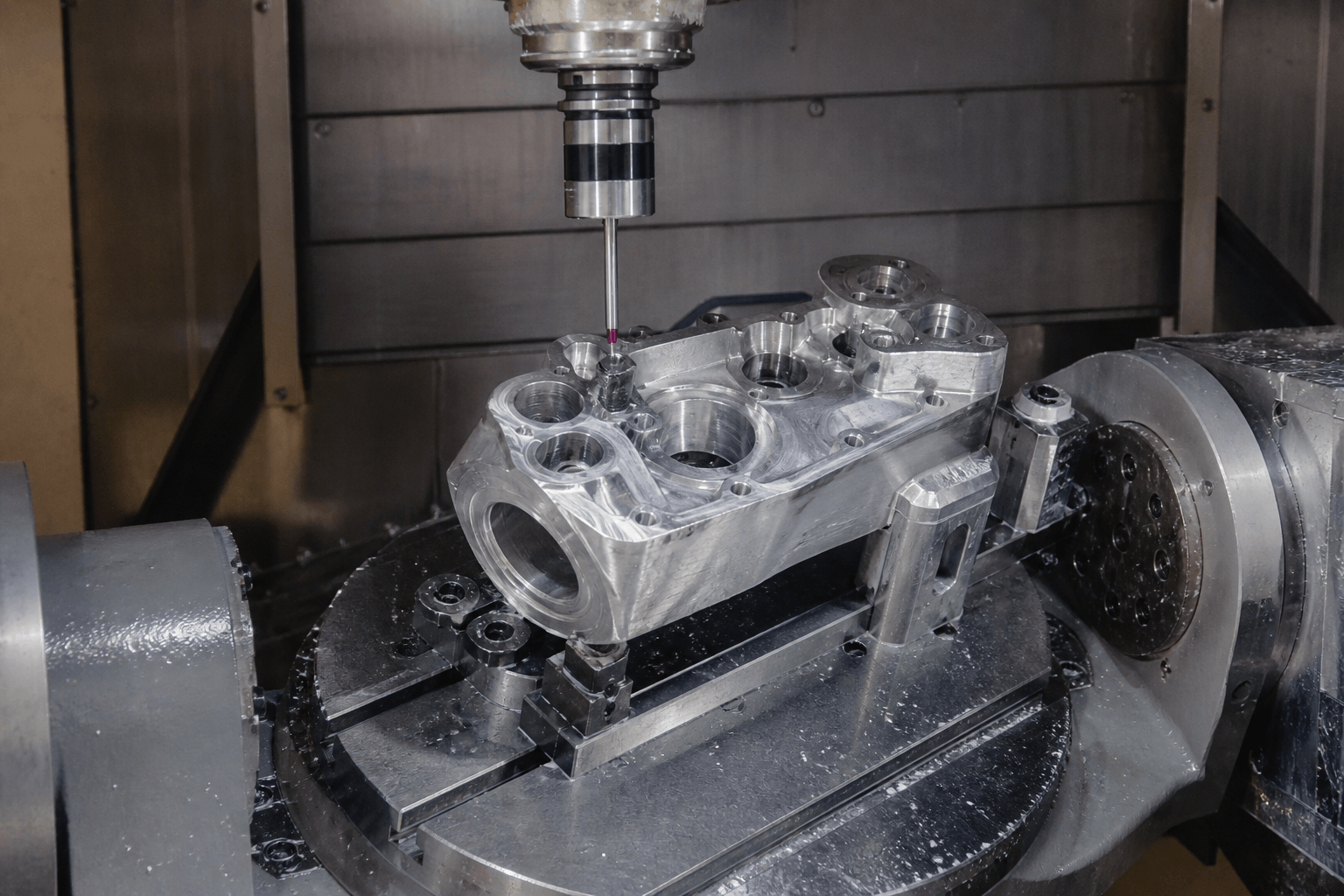
Where appropriate, probing can establish or check workpiece location and support in-process verification. It does not replace final dimensional inspection when the drawing or quality plan requires it. Final checks should relate measurements to the specified datums and use methods suitable for the geometry and tolerance requirements. Fewer setups may reduce the number of datum transfers, but inspection remains necessary to confirm the finished part.
When 5th axis machining is worth considering
| Decision factor | 5-axis may be worth evaluating when… | A simpler approach may fit when… |
|---|---|---|
| Geometry and access | Compound surfaces, angled features, or undercuts require changing the tool or part orientation. | Critical features are accessible with a stable three-axis approach. |
| Setups and datums | Multiple faces need related features and repeated reclamping would complicate datum control. | Separate setups are straightforward and references can be transferred and verified. |
| Material and workholding | Fixture and tool access can be planned around the material and cutting loads. | Rotary motion restricts support, clearance, or measurement access. |
| Programming and verification | The toolpath, post-processor, simulation, and inspection plan can be validated for the machine. | Added programming and setup demands do not solve a meaningful geometry or process problem. |
For a feasibility review, provide the part drawing or 3D CAD model, material and condition, critical dimensions and surface requirements, estimated quantity, and target timing. These details help an engineering team assess geometry, workholding, machining strategy, and verification needs. Yishang supports OEM and ODM custom manufacturing projects; a review can help determine whether the project fits a machining or broader metal-manufacturing route.
Frequently Asked Questions
Is 5th axis machining the same as simultaneous 5-axis machining?
No. The term 5th axis machining can refer broadly to using two rotary axes with three linear axes. In indexed 3+2 machining, the rotary axes position the tool or part before cutting at a fixed angle. Simultaneous 5-axis machining moves rotary and linear axes together while cutting.
Does 5-axis machining always require fewer setups than 3-axis machining?
No. It can combine access to multiple sides or orientations in one fixture, but part geometry, machine configuration, workholding, and inspection access determine whether setups are actually reduced. A 3-axis process may remain simpler for parts whose features are already accessible.
Can 5-axis machining handle titanium and Inconel?
These materials can be machined with suitable equipment and process planning, but feasibility depends on the specific alloy, stock condition, part geometry, tooling, workholding, and required inspection. The added axes improve orientation options; they do not remove concerns such as heat, tool wear, or chip evacuation.
How does 5-axis machining differ from 6-axis or 7-axis CNC equipment?
A five-axis machining center coordinates three linear axes and two rotary axes for milling operations. Six- and seven-axis equipment adds further movement axes, often for specialized kinematics or coordinated operations. Axis count alone does not establish that a machine can perform a particular task; the machine type, working envelope, tools, and process determine suitability.
Evaluate the geometry and verification plan together with the machine motion. The right process is the one that can reach the required features, hold the part securely, and confirm the specified dimensions without adding unnecessary complexity.