
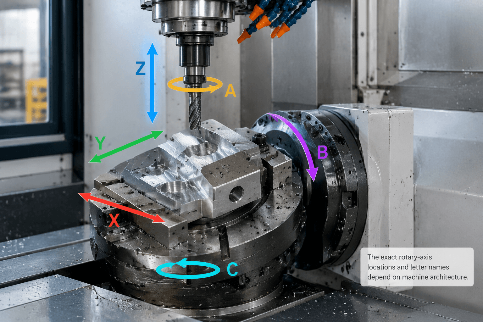
A 6 axis milling machine controls six motion axes, commonly three linear axes and three rotary axes, to position the cutting tool relative to the workpiece. The physical arrangement differs among machines, and having six controlled axes does not necessarily mean that all six move simultaneously while cutting.
The sixth degree of freedom can expand the available tool-approach directions, but axis count alone does not establish whether a machine is suitable, accurate, fast, or economical for a particular part. The practical value depends on machine kinematics, geometry access, workholding, tooling, software, and the required machining sequence.
What Counts as the Sixth Axis?
A conventional three-axis milling machine moves along three perpendicular linear directions. These are normally labeled X, Y, and Z. Additional rotary axes turn around one or more of those linear axes:
Linear movement
- X: left-to-right movement
- Y: front-to-back movement
- Z: up-and-down movement
Typical rotary notation
- A: rotation around X
- B: rotation around Y
- C: rotation around Z
The rotary movement may come from a tilting spindle head, a rotating table, a trunnion, a workpiece positioner, or a combination of tool-side and table-side mechanisms. Consequently, two machines described as six-axis can create very different tool-to-part motion.
It is also important to separate degrees of freedom from simultaneous interpolation. In indexed machining, rotary axes position the part or tool at a selected angle and then remain stationary while linear cutting takes place. In simultaneous machining, several linear and rotary axes move together along a programmed toolpath. A machine may have six controllable axes but use only a subset of them simultaneously for a given operation.
Where the Rotary Axes Can Be Located
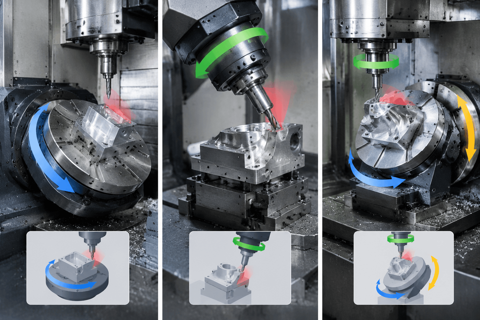
Machine architecture determines which mass moves, how the cutter approaches the part, and where interference may occur. The following configurations illustrate the main concepts rather than defining every machine sold under the six-axis label.
| Configuration | What supplies rotary motion? | Process implications to evaluate |
|---|---|---|
| Table-side rotary system | The table, trunnion, or workpiece rotates and tilts. | Offers multiple workpiece orientations, but the fixture and part must remain within rotary load, travel, and clearance limits. |
| Tool-side rotary system | The spindle head or tool assembly provides several angular movements. | Can orient the cutter around a relatively stationary part. Head size, spindle geometry, tool-holder clearance, and rigidity still affect access. |
| Split tool/table system | Rotary movements are divided between the spindle side and workpiece side. | May provide useful approach combinations, although the CAM system and post-processor must model the specific kinematic chain. |
| Articulated or specialized architecture | Linked joints or another mechanism create the commanded motion. | The usable workspace, stiffness, control behavior, and terminology can differ substantially from a conventional machining center. |
Architecture affects more than nominal axis count. A fixture can block an otherwise available direction. A rotary axis may reach its travel limit before the tool reaches the feature. Tilting can also move the workpiece outside the usable envelope or bring the spindle, holder, table, fixture, and part into conflict.
For this reason, a machine specification should identify the kinematic arrangement, rotary ranges, permitted simultaneous combinations, work envelope, and control functions. A generic statement such as “six-axis capability” is not enough to confirm part feasibility.
3-Axis, 5-Axis, and 6-Axis Milling Compared
The simplest viable process is usually determined by required approach directions rather than by the visual complexity of the CAD model.
| Consideration | 3-axis milling | 5-axis milling | 6-axis milling |
|---|---|---|---|
| Typical motion concept | Three linear axes | Three linear plus two rotary axes | Commonly three linear plus three rotary axes |
| Tool orientation | Usually fixed relative to the setup | Tool or part can be oriented through two rotary freedoms | An additional controlled rotary freedom may expand orientation options |
| Multi-face access | Often requires repositioning or separate fixtures | Can reach several faces where machine travel and clearance permit | May provide another path around fixture, part, or spindle interference |
| Programming | Generally less kinematically complex | Requires machine-aware programming for indexed or simultaneous motion | Requires an accurate model of the complete six-axis kinematic chain |
| Best fit | Accessible prismatic features and faces that can be set up directly | Parts needing varied tool angles or consolidated multi-face machining | Parts that obtain a demonstrable access or orientation benefit from the extra freedom |
Consider a hypothetical housing with a top cavity, holes on four side faces, an angled sealing surface, and an internal undercut. A three-axis strategy could machine the top, then use additional setups for the sides and angled face. The internal undercut would need a suitable cutter and a clear entry path.
A 5-axis milling machine might orient the same housing so that the top, side holes, and angled face can be reached in fewer clampings. If its two rotary axes provide sufficient approach vectors and clearance, adding another axis would not improve the process merely because the housing looks complicated.
Six-axis motion becomes relevant if the remaining rotary freedom lets the tool approach the internal feature, maintain a required orientation around an obstruction, or avoid a kinematic limit that prevents the five-axis strategy. Even then, cutter shape, holder clearance, fixture access, and machine travel must support the planned path.
Geometries That May Benefit from a Sixth Degree of Freedom
The additional axis is most useful when it changes a specific access problem. It should not be justified only by the number of surfaces in the model.
- Undercuts: A further rotary movement may place an undercut cutter behind a wall or flange. The entry path and withdrawal path must remain collision-free.
- Deep cavities: Reorienting the part or spindle may allow a shorter tool to approach a deep feature more directly. Whether this is possible depends on the cavity opening, holder diameter, spindle body, and machine travel.
- Compound curves: Coordinated movement can maintain a changing tool orientation along an airfoil-like or freeform surface. Five axes may already provide the necessary tool vector; the sixth is useful only if it resolves an additional orientation or access constraint.
- Internal features: Internal channels, back-side details, and intersecting passages can require unusual approach directions. No axis arrangement can overcome a physically closed path or a cutter that cannot fit through the opening.
- Multi-face parts: Brackets, housings, and structural components may expose several faces in one fixture. Setup consolidation is possible only when the fixture leaves those faces accessible and the rotary motions stay within the machine envelope.
Reducing reclamping can also reduce the number of datum transfers between operations. This may simplify alignment control, but it does not guarantee a particular tolerance or surface finish. Cutting forces, thermal behavior, tool deflection, rotary positioning behavior, stock condition, and inspection strategy remain relevant.
In a hypothetical setup comparison, a three-axis route might require dedicated orientations for the top, front, rear, and angled faces. A multi-axis route could potentially expose those faces from one primary workholding position. However, a second setup may still be necessary to remove the fixture interface or machine the clamped surface.
Does This Feature Need 3, 5, or 6 Axes?
This part-to-axis decision matrix is a screening tool, not a substitute for machine-specific simulation.
| Part or feature condition | First strategy to evaluate | Reason |
|---|---|---|
| Features are accessible from one direction | 3-axis | Additional rotary movement may add programming and setup complexity without improving access. |
| Several planar faces require machining | Indexed 4- or 5-axis | Positional rotation may expose the faces without continuous rotary cutting. |
| Tool angle changes continuously over a curved surface | Simultaneous 5-axis | Two rotary freedoms may provide the required orientation throughout the path. |
| A five-axis path reaches a rotary limit or fixture obstruction | Evaluate 6-axis | The extra degree of freedom may offer an alternative orientation while preserving the toolpath objective. |
| Internal or back-side feature has a restricted opening | Geometry and collision study | Axis count cannot compensate for an impossible cutter-entry path. |
| Part is simple but produced in high volume | Compare complete process plans | Dedicated fixtures, multiple simpler machines, or automation may be more appropriate than added kinematic freedom. |
Before selecting a process, check five connected areas:
- Part definition: Review the 3D model, dimensions, datum structure, critical tolerances, required surface condition, material, stock form, and quantity.
- Machine kinematics: Confirm which component supplies each movement, rotary travel limits, simultaneous-axis capability, work envelope, and potential singular or restricted positions.
- Tooling and fixturing: Model the cutter, holder, spindle body, clamps, jaws, supports, and stock. Tool reach should be considered together with deflection and clearance.
- CAM and control: Use a post-processor developed for the actual machine configuration. Generic axis output may not represent the real pivot points, limits, or motion sequence.
- Verification: Run machine-level collision checking and review safe approach, retract, indexing, and tool-change movements. Plan how difficult features and datum relationships will be inspected.
A capable five-axis strategy may remain simpler when the sixth degree of freedom does not change access, setup count, or tool orientation. Conversely, a six-axis concept deserves evaluation when simulation shows a clear route around a specific restriction.
Frequently Asked Questions
How much does a 6 axis CNC milling machine cost?
There is no meaningful universal price. Cost depends on machine architecture, work envelope, spindle specification, control system, rotary mechanisms, automation, software, post-processor development, tooling, installation, training, service, and regional support. Buyers should compare total process requirements and expected utilization rather than axis count alone.
What is the key difference between 5-axis and 6-axis milling?
Six-axis milling adds another controllable degree of freedom. That additional motion may expand tool or workpiece orientation, but its value depends on the kinematic arrangement and the geometry being machined. Many complex parts remain fully feasible with a well-planned five-axis process.
Does a 6 axis milling machine always move all six axes at once?
No. Some operations use indexed positioning, in which rotary axes move to an angle and then stop during cutting. Other operations interpolate several axes simultaneously. The machine control, mechanical architecture, CAM output, and programmed operation determine which axes move together.
Are there 7-axis CNC machines, and are they automatically more capable?
Machines and manufacturing systems with seven or more controlled axes exist, but terminology varies among milling centers, robotic systems, and mill-turn equipment. These processes are not interchangeable. More axes do not automatically provide better accuracy, productivity, or suitability; usable kinematics, rigidity, access, software, tooling, and the part requirement remain decisive.