
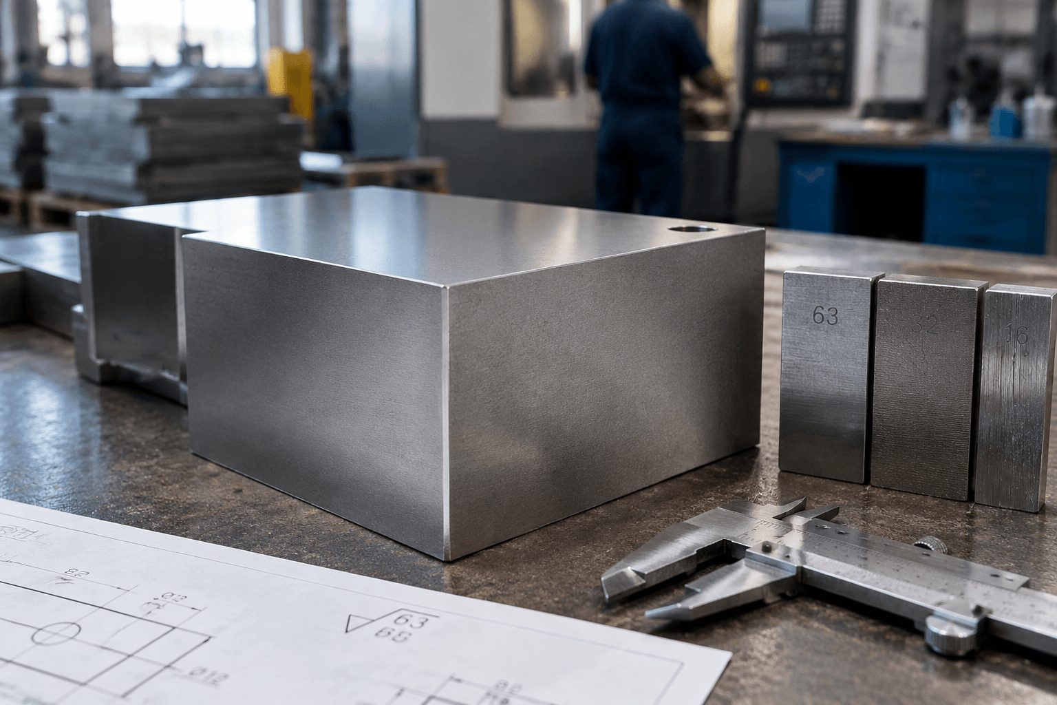
A 63 finish usually means a surface roughness of 63 microinches Ra, equivalent to approximately 1.6 micrometres Ra. It is a measurable surface roughness requirement—not a color, coating, gloss level, or general description of how a part should look.
This finish is common enough to appear on machined faces, mounting surfaces, bosses, shafts, and other functional features. However, specifying it correctly requires more than placing “63” on a drawing. The units, roughness parameter, measurement area, surface function, manufacturing process, and inspection method all influence whether the requirement is clear and appropriate.
What Does a 63 Surface Finish Mean?
Surface roughness describes the fine peaks and valleys left by cutting tools, abrasives, forming operations, or other manufacturing processes. Ra, or arithmetic average roughness, summarizes the average deviation of the measured profile from its mean line over a defined evaluation length.
In US customary drawing practice, the number 63 commonly refers to 63 microinches Ra, often written as 63 µin Ra. Converting the units gives:
63 µin Ra × 0.0254 = 1.6002 µm Ra
For practical drawing and inspection purposes, this is normally expressed as 1.6 µm Ra. Therefore, “63 microinch surface finish,” “63 Ra surface finish,” and “1.6 µm Ra” may describe the same roughness target when Ra is explicitly identified.
| Common inch-unit callout | Approximate metric equivalent | Relative roughness |
|---|---|---|
| 125 µin Ra | 3.2 µm Ra | Rougher than 63 |
| 63 µin Ra | 1.6 µm Ra | Moderate machined finish |
| 32 µin Ra | 0.8 µm Ra | Smoother than 63 |
| 16 µin Ra | 0.4 µm Ra | Finer finish requiring more process control |
These numerical comparisons do not establish which finish is suitable for a particular component. A rougher surface may be acceptable on a clearance feature, while a sealing face or sliding interface may need a smoother value and additional controls.
A bare “63” can also be ambiguous. If the drawing does not state Ra, the applicable unit system, or the intended surface, the manufacturer should request clarification rather than assume. The number could otherwise be confused with an RMS value, a metric value, a hardness reference, or another drawing note.
How to Decide Whether 63 Ra Is Appropriate
The right roughness is determined by the function of the individual surface, not by a general preference for smoother parts. Requiring 63 Ra on every face may add machining and inspection work without improving performance.
Review the following considerations before selecting the value:
- Static mounting faces: A 63 finish may be appropriate where parts require controlled contact but do not form a critical seal. Flatness and parallelism may still matter more than average roughness.
- Sliding or rotating contact: Roughness can influence friction, lubricant retention, wear, and running behavior. Ra alone may not fully describe deep valleys or isolated peaks.
- Sealing surfaces: The acceptable texture depends on seal type, pressure, material, direction of lay, and mating component. A 63 Ra value should not be assumed suitable for every gasket, O-ring, or metal-to-metal seal.
- Bearing or press-fit locations: Roughness interacts with dimensional tolerance and the effective contact between components. The fit specification and surface requirement should be reviewed together.
- Cosmetic panels: Ra does not fully define visual uniformity. Grain direction, waviness, scratches, polishing method, coating, and color may require separate notes or an approved appearance sample.
- Adhesive or coating preparation: A smoother surface is not automatically better. The preparation requirement should reflect the coating or bonding process rather than an unrelated machining convention.
It is also important to distinguish roughness from other surface characteristics. Ra does not control flatness, waviness, dents, burrs, tool chatter, lay direction, or isolated defects unless these are addressed separately. Two surfaces can report the same Ra value while looking different or performing differently because their peak-and-valley patterns are not the same.
From a sourcing perspective, avoid tightening a requirement from 125 to 63, or from 63 to 32, without a functional reason. Each change halves the numerical Ra limit, but it does not produce a predictable cost percentage. The effect depends on material, feature accessibility, starting condition, tooling, machining strategy, part rigidity, inspection needs, and production quantity.
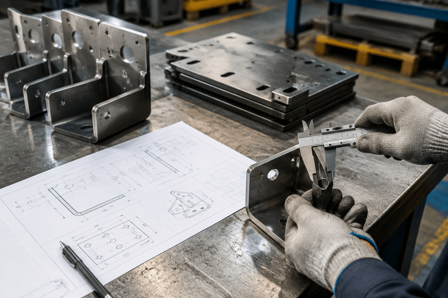
How the Manufacturing Process Affects a 63 Finish
A 63 finish is often associated with machining, but the achievable texture depends on how the feature is produced. Tool geometry, feed rate, cutting speed, tool condition, workholding, vibration, coolant strategy, and material behavior can all affect the resulting profile.
Milling may produce a directional pattern determined by the cutter path and step-over. Turning creates circumferential tool marks on cylindrical components. Grinding can generate a finer and more uniform texture, although it adds a separate operation. Abrasive finishing may reduce prominent peaks but can also round edges or alter dimensions if not controlled.
Material is equally important. Aluminum, stainless steel, carbon steel, brass, and coated materials do not respond identically to cutting or abrasion. Even within one material family, hardness, temper, inclusions, and work-hardening behavior can change the result. For this reason, a supplier should evaluate the specified value against the actual alloy, geometry, and process rather than provide a universal assurance.
For sheet metal products, distinguish the supplied sheet texture from any locally finished features. Flat sheet generally begins with a mill, rolled, brushed, or coated texture; fabrication alone does not establish a controlled 63 µin Ra surface across the sheet.
An assembly may contain mounting pads, spacers, or bushings whose functional surfaces require 63 Ra. Identify those surfaces on the drawing and assess their finishing and inspection needs individually, rather than applying the requirement to the entire assembly.
Drawing and Inspection Requirements for a 63 Finish
A useful drawing callout should communicate a measurable requirement. At minimum, identify the roughness parameter and units, such as Ra 1.6 µm maximum or Ra 63 µin maximum, and apply the surface texture symbol or leader to the relevant face.
Using “maximum” is important when that is the design intent. A nominal value of 1.6 µm without an acceptance direction can leave uncertainty about whether smoother surfaces are acceptable. In some applications, an excessively smooth surface may also be undesirable because the interface depends on lubricant retention, coating adhesion, or controlled texture. Such cases may require an upper and lower roughness range rather than only a maximum.
For functionally critical areas, the drawing or inspection plan may also need to define:
- The exact surface or zone to be measured.
- Ra, Rz, or another required roughness parameter.
- Whether the value is a maximum, minimum, or bounded range.
- Required lay direction where machining marks affect sealing or movement.
- Locations and number of measurements.
- Cutoff, filter, and evaluation-length settings where necessary for consistent results.
- Whether scratches, pits, burrs, chatter, or other defects have separate acceptance criteria.
A contact profilometer is commonly used to evaluate machined roughness. Before measuring, the surface should be clean and accessible, and the instrument should be suitable and calibrated for the required range. The stylus traverse is generally oriented across the predominant lay where practical, because measuring parallel to the tool marks can produce a different result. Multiple readings may be necessary where texture varies across the feature.
Ra should not be treated as a complete description of the profile. Rz evaluates peak-to-valley characteristics using a different calculation approach and can reveal profile differences that average roughness may conceal. This can be useful when deep scratches, pronounced peaks, sealing behavior, or wear initiation are concerns. However, there is no universal conversion factor between Ra and Rz. Any ratio is influenced by the process and actual profile shape, so acceptance should be based on the parameter specified on the drawing.
Agreement before production is especially valuable when a 63 finish applies to a difficult-to-access pocket, a thin part susceptible to vibration, a welded surface, or a feature requiring finishing after coating. Inspection access should be considered during design because a surface cannot be verified reliably if the measuring instrument cannot reach it.
Frequently Asked Questions
Is a 63 finish the same as 1.6 µm Ra?
Yes, when 63 means 63 microinches Ra. The exact mathematical conversion is 1.6002 µm Ra, normally rounded to 1.6 µm Ra. Confirm the parameter and units because an isolated “63” is not a complete specification.
Is 63 Ra the same as 63 RMS?
No. Ra and RMS, also called Rq in many roughness contexts, use different mathematical calculations. Their values may be relatively close for some profiles, but they are not interchangeable and there is no fixed conversion that applies to every manufactured surface.
What abrasive grit produces a 63 Ra finish?
There is no reliable one-to-one conversion between abrasive grit and Ra. A stated grit size describes the abrasive, while the resulting roughness also depends on the material, starting surface, abrasive condition, pressure, speed, lubrication, stroke direction, and finishing time. A 240-grit process, for example, cannot be assumed to produce a specific Ra value without measurement.
Is a 63 finish suitable for an O-ring sealing surface?
A 63 µin Ra value alone is not enough to decide. Check the seal supplier’s requirements for the specific seal material and whether the seal is static or dynamic. Lay direction, scratches, and other texture characteristics may also affect sealing, so confirm those requirements before accepting 63 Ra as the drawing limit.