
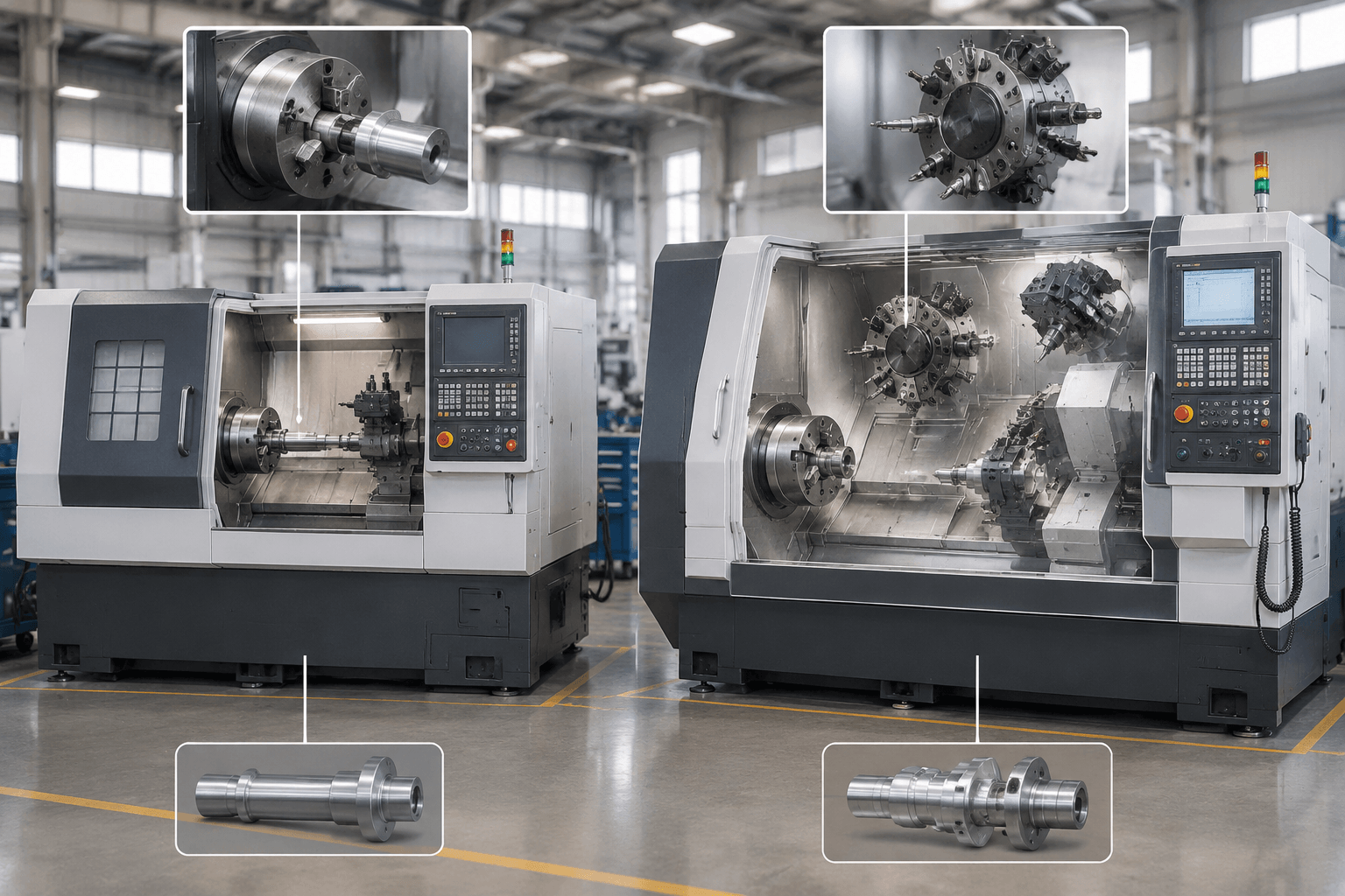
Advanced CNC lathe machines combine controlled turning with additional axes, spindles, driven tooling, automation, or monitoring systems to machine more complex rotational parts. The right machine is not necessarily the largest or the one with the most axes; suitability depends on part diameter, length, material, features, tolerances, production quantity, workholding, and required secondary operations.
Machine descriptions often emphasize swing, spindle power, speed, axis count, and machining length. These figures are useful, but none proves that a machine can produce a specific component consistently. Technical buyers should interpret the complete configuration in relation to the drawing, process sequence, tooling access, inspection requirements, and production workflow.
What Defines an Advanced CNC Lathe?
A basic CNC turning machine commonly controls movement along the X and Z axes. The workpiece rotates in the spindle while stationary tools remove material to create external diameters, bores, grooves, threads, tapers, and facing features.
An advanced CNC lathe extends this foundation. Depending on its configuration, it may include driven tools for drilling or milling, a Y-axis for off-center features, a sub-spindle for machining the back of a part, multiple turrets, or additional rotary and linear axes. Automation systems may load stock, transfer components, measure tools, monitor machining conditions, or remove completed parts.
The word “advanced” is therefore a functional description rather than a reliable performance category. A machine with additional axes can combine more operations, but the value of those axes depends on whether the component actually requires them. A stable two-axis turning center may be appropriate for a straightforward shaft or bushing, while a part with cross-holes, flats, eccentric features, and back-side details may justify a more integrated platform.
CNC turning generally produces rotational geometry from bar, tube, billet, forging, or casting. It should not be treated as interchangeable with sheet metal fabrication, which serves different part geometries and production requirements.
Comparing CNC Lathe Configurations
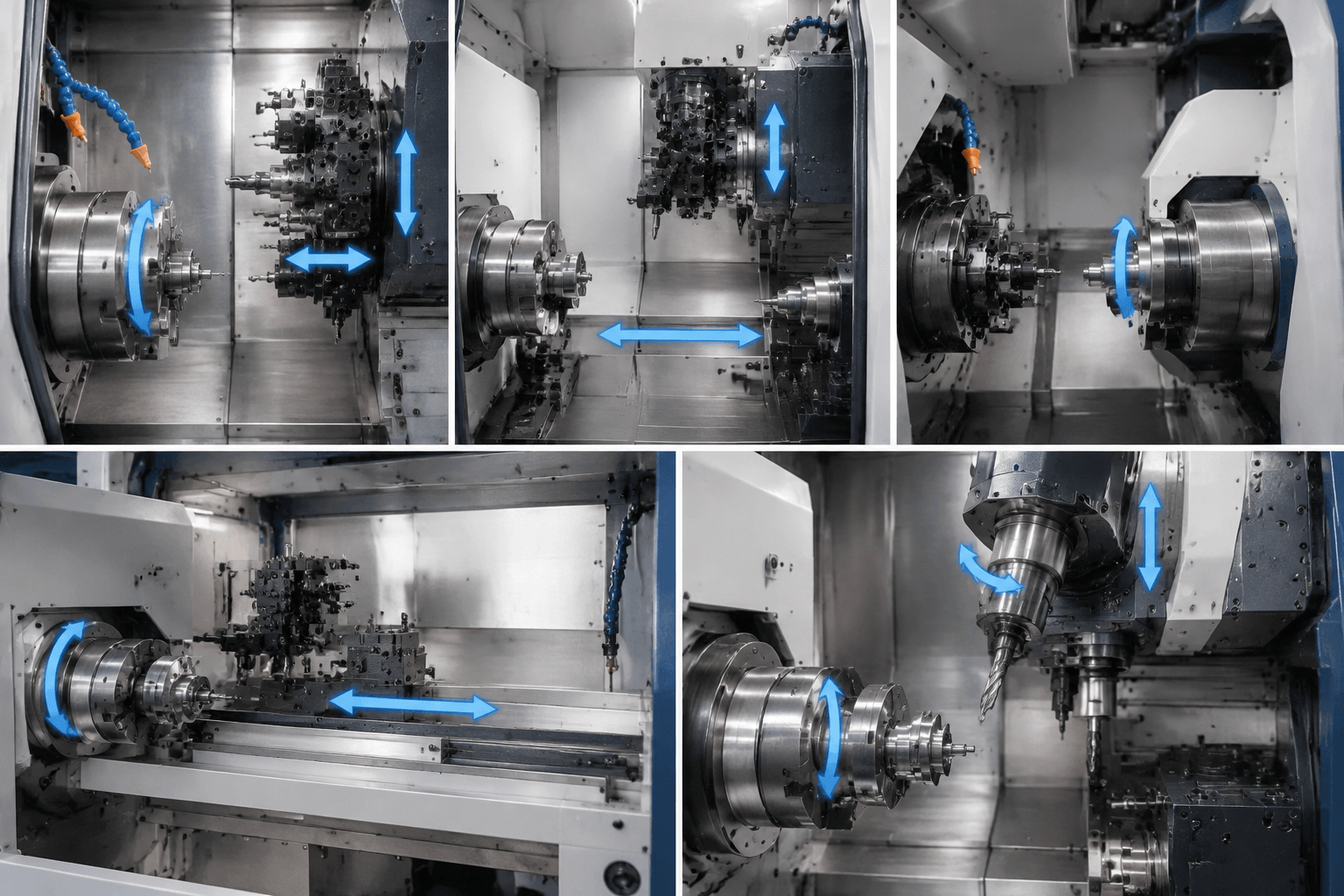
Machine architecture determines which operations can be completed in one setup and how easily tools can reach each feature. The following comparison focuses on functional differences rather than model rankings.
| Configuration | Principal capability | Representative part requirements | Important trade-offs |
|---|---|---|---|
| Standard turning center | Two-axis turning with a main spindle and turret | Concentric diameters, bores, grooves, threads, tapers, and facing | Simple process planning, but milled or off-axis features normally require another setup or machine |
| Live-tool lathe | Rotating tools perform drilling, tapping, and limited milling while the workpiece remains clamped | Axial holes, radial holes, slots, wrench flats, and light milled details | Tool speed, torque, rigidity, orientation control, and access may limit the milling work |
| Y-axis turning center | Adds controlled motion perpendicular to the usual X-Z turning plane | Off-center holes, asymmetric slots, keyways, pockets, and features requiring tool-center offset | More programming and collision-management requirements; usable travel and tooling clearance must be checked |
| Sub-spindle machine | Transfers the component from the main spindle for back-side machining | Parts requiring completed features on both ends without manual reclamping | Transfer accuracy, gripping length, workholding marks, and access to the second operation affect suitability |
| Twin-turret machine | Uses two tool carriers, sometimes simultaneously or on separate spindles | Parts with many operations or workflows that benefit from coordinated tool engagement | Process balancing, interference zones, programming, and tooling investment become more demanding |
| Swiss-type lathe | Supports bar stock close to the cutting zone with a guide bushing or comparable sliding-headstock arrangement | Long, slender, small-diameter parts with multiple detailed features | Material straightness, bar preparation, guide-bushing compatibility, remnant control, and part geometry require careful review |
| Multitasking turn-mill platform | Combines turning with broader milling capability, often through a milling spindle and multiple controlled axes | Complex components with rotational and prismatic features that would otherwise need several machines | Higher integration does not remove the need for suitable workholding, tooling, programming, inspection, or process validation |
A live-tool lathe and a turn-mill platform can overlap in function, but they are not automatically equivalent. Live tooling adds rotary cutting to a turning center. A turn-mill platform generally provides a wider milling work envelope, axis movement, tool orientation, or tool-changing strategy. Buyers should examine the required operations rather than relying on the category name.
From Machine Specification to Part Suitability
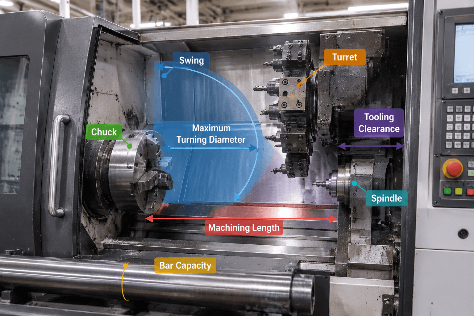
Headline specifications describe boundaries and resources. They must be interpreted together because nominal capacity may differ from the usable envelope once the chuck, jaws, turret, toolholders, tailstock, sub-spindle, steady rest, and component geometry are considered.
| Machine specification | What it describes | How it influences application fit | What must also be checked |
|---|---|---|---|
| Swing | The maximum diameter that can physically rotate over a stated machine area | Provides an initial indication of whether a workpiece or fixture can rotate without interference | Swing does not equal maximum cutting diameter; verify chuck jaws, tooling, guards, and turret clearance |
| Maximum turning diameter | The stated diameter that can be machined under defined conditions | More directly relates to the intended cut than swing | Part profile, toolholder size, adjacent features, jaw projection, and operation sequence |
| Machining length | The available longitudinal working distance | Indicates whether the tool can reach the required axial features | Chuck engagement, tool overhang, tailstock use, sub-spindle position, and unsupported length reduce usable space |
| Spindle power and torque | The spindle’s capacity to drive cutting under specified speed conditions | Affects feasible material-removal strategies, especially for larger diameters or demanding materials | Torque curve, duty rating, cutting speed, insert geometry, machine rigidity, workholding, and part stability |
| Maximum spindle speed | The upper rotational-speed limit | Can support appropriate cutting speeds for smaller diameters and certain materials | Chuck rating, bar condition, imbalance, workpiece diameter, tooling, heat, and surface requirements |
| Chuck size | The nominal size of the primary workholding device | Influences gripping range, jaw options, and compatibility with workpiece dimensions | Required grip length, distortion risk, jaw design, clamping force, runout, and accessibility |
| Bar capacity | The maximum stock diameter that can pass through the spindle bore or bar system | Helps determine whether components can be produced from continuous bar feed | Draw-tube restrictions, liner requirements, bar straightness, feeder compatibility, and finished-part diameter |
| Axis configuration | The number and type of controlled motions | Determines which feature orientations and combined operations are possible | Axis travel, interpolation, synchronization, collision zones, programming support, and actual feature access |
| Turret and tooling system | The number, type, size, and arrangement of tool stations | Affects operation coverage, changeover planning, rigidity, and tool accessibility | Driven-tool specifications, holder availability, neighboring-station interference, coolant delivery, and presetting |
More capacity is not automatically better. A large swing does not guarantee suitable cutting access, greater spindle power does not establish accuracy, and a high axis count does not compensate for weak workholding or an unstable process. Machine specifications should narrow the candidate field; they should not replace a drawing-based engineering review.
Controls, Automation, Workholding, and Process Verification
The mechanical layout is only one part of an advanced turning process. The CNC control coordinates axes, spindle orientation, tool offsets, synchronization, canned cycles, and program execution. Its usefulness depends on supported functions, post-processing, simulation practices, programming quality, and the operator’s ability to manage tools and offsets.
Tool setters can establish or verify tool positions. Workpiece probes may locate a feature or support in-process checks where the machine and process allow. Tool-life monitoring can trigger warnings or replacement routines based on time, part count, load, or other configured conditions. These functions help manage variation, but they do not independently certify the finished component.
Bar feeders, gantry loaders, robots, parts catchers, conveyors, and pallet systems can reduce manual handling and support longer production sequences. Their effectiveness depends on reliable stock presentation, chip evacuation, coolant control, part transfer, tool life, and recovery procedures. Automation can repeat a poor setup just as consistently as a good one, so process validation remains essential.
Workholding is equally important. Standard jaws, bored soft jaws, collets, expanding mandrels, fixtures, tailstocks, and steady rests solve different locating and support problems. Selection must account for cutting forces, part distortion, grip length, datum strategy, surface protection, and access to the required features.
Final inspection remains a separate verification activity. Machine probing can support control and adjustment, while calibrated inspection equipment verifies dimensions and characteristics according to the drawing and inspection plan. Accuracy and repeatability depend on the full system: machine condition, thermal behavior, setup stability, tooling, workholding, programming, material behavior, inspection method, and operator control.
How to Match a Machine to the Part
Begin with the component rather than the machine brochure. Review the drawing and 3D model together, identifying the primary turning axis, stock form, maximum and minimum diameters, overall length, unsupported sections, internal features, cross-holes, milled faces, threads, grooves, and back-side details.
Next, map the operation sequence. A concentric sleeve may need only turning and boring. A shaft with flats and radial holes may suit a live-tool or Y-axis machine. A component requiring complete machining on both ends may benefit from a sub-spindle. A long, slender precision component may justify evaluating a Swiss-type process. A part combining complex turned surfaces with substantial prismatic milling may require a turn-mill platform or separate turning and milling operations.
Material also changes the decision. Strength, hardness, abrasiveness, chip behavior, heat generation, and stock condition influence spindle load, tool selection, workholding, coolant strategy, and achievable process stability. Surface finish and dimensional requirements must be connected to specific features because some may require grinding, honing, lapping, or another secondary process after turning.
Production quantity affects setup economics and automation choices. A low-volume complex part may favor flexible tooling and accessible setup changes. A recurring bar-fed component may justify more dedicated workholding, tool monitoring, or automated handling. Neither approach is inherently superior; each should reflect the expected product mix and changeover frequency.
Machine capacity should finally be separated from demonstrated process capability. A machine may have enough travel and power to contain the component, yet the supplier still needs an appropriate fixture, tool plan, program, inspection method, and stable production route. Critical dimensions, datum relationships, runout requirements, surface specifications, and downstream interfaces should therefore be reviewed together.
Clarify the manufacturing route before selecting a machine category. For a technical consultation on application fit, share the part drawing or 3D model, material specification, critical dimensions and tolerances, expected quantity, and required downstream operations. These inputs help determine whether the geometry calls for conventional turning, an integrated advanced-lathe configuration, or a separate secondary operation.
Frequently Asked Questions
What makes a CNC lathe an advanced machine?
An advanced CNC lathe adds functional capability beyond basic two-axis turning. This may include live tooling, Y-axis movement, a sub-spindle, multiple turrets, broader milling functions, automated loading, probing, or process monitoring. The relevant definition depends on what these systems contribute to the intended part.
Is a turn-mill machine the same as a CNC lathe with live tooling?
Not necessarily. Both can perform turning and rotary-tool operations, but a turn-mill platform may provide more extensive milling travel, tool orientation, interpolation, or automatic tool-changing capability. The distinction should be based on configuration and required operations, not terminology alone.
Does greater spindle power make a CNC lathe more accurate?
No. Power affects the ability to drive a cut under specified conditions, but accuracy also depends on machine condition, rigidity, thermal stability, workholding, tooling, programming, material behavior, setup control, and inspection. Additional power cannot correct an unsuitable process.
When is a Swiss-type lathe preferable to a conventional turning center?
A Swiss-type machine is often considered for long, slender, small-diameter parts because it supports the stock close to the cutting zone. Suitability still depends on geometry, material, guide-bushing requirements, stock quality, tooling access, batch size, and the complete operation sequence.